


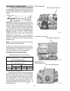
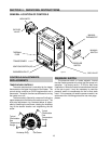
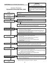
BURNER DRAWER REMOVAL
1. Shut off main electrical power switch to heater.
2. Shut off gas upstream of heater.
3. Remove front door.
4. Disconnect gas line from gas valve.
5. Remove (2) screws that mount burner tray to unit.
6. Disconnect wires that terminate at gas valve.
7. Slide out burner tray.
8. Reverse above procedure to reinstall.
GAS VALVE REMOVAL
1. Remove burner tray. (See burner tray removal
procedure).
2. Disconnect pilot tubing from gas valve.
3. Remove gas valve with manifold from burner tray.
4. Remove manifold from gas valve.
5. Reverse above procedure to re-install.
MAIN BURNER AND ORIFICE REMOVAL
1. Remove burner drawer. (See burner drawer re-
moval procedure).
2. Remove screws and burner hold down bracket.
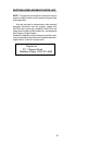
NOTE:
If the heat exchanger is sooted badly, the
burner hold down bracket and spacer can become
distorted from direct flame impingement and this usu-
ally necessitates replacement of these parts.
3. Lift burners from slotted spacers and slide from
orifices. Clean with a wire brush.
4. Orifices usually do not need to be replaced. To
clean, run either copper wire or wood toothpick
through orifice. Do not enlarge hole. To remove
orifice, use a socket wrench and remove from
manifold. DO NOT overtighten when reinstalling.
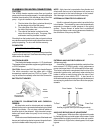
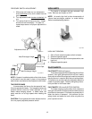
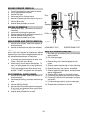
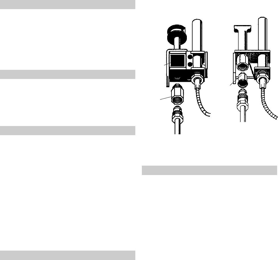
PILOT REMOVAL AND CLEANING
1. Remove burner drawer. (See burner drawer re-
moval procedure).
2. Disconnect pilot tubing, disconnect wires from gas
valve.
3. Disconnect pilot bracket from burner shield.
4. Remove pilot from bracket.
5. Remove pilot orifice and air opening (Honeywell
MV unit only), and clean with wire or small brush.
CAUTION! DO NOT enlarge hole in pilot orifice.
6. Reverse above procedure to re-install.
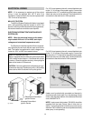
HEAT EXCHANGER REMOVAL
1. Shut water, gas, and electricity off, close valves and
relieve pressure.
2. Drain heat exchanger.
3. Loosen and remove flange bolts.
4. Remove flange and inlet/outlet pipes from the
header.
5. Remove outdoor stackless top or indoor stack top
from unit.
6. Remove jacket top, flue collector, and baffles.
7. Remove upper front jacket panel, and disconnect
wires at toggle switch.
8. Remove capillary bulb from inlet/outlet header.
9. Disconnect press switch tube from return header.
10. Disconnect hi-limit wire from thermostat, and pres-
sure switch.
11. Lift heat exchanger straight up from combustion
chamber, using caution not to damage refractory.
12. Reverse above procedure to re-install.
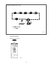
Pilot Pilot
Air
Opening
Orifice
Orifice
HONEYWELL PILOT ROBERTSHAW PILOT
Fig. # 8045.1
Fig. # 8102.0s
20