


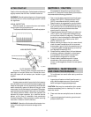
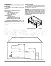
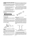
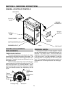
GAS SUPPLY CONNECTIONS
Gas piping must have a sediment trap ahead of
the heater gas controls, and a manual shut-off valve
located outside the heater jacket. All gas piping should
be tested after installation in accordance with local
codes.
CAUTION:
The heater and its manual shut off valve
must be disconnected from the gas supply during any
pressure testing of that system at test pressures in
excess of 1/2 psig (3.45 KPA). Dissipate test pressure
in the gas supply line before reconnecting the heater
and its manual shut off valve to gas supply line.
FAILURE TO FOLLOW THIS PROCEDURE MAY
DAMAGE THE GAS VALVE. OVER PRES-
SURED GAS VALVES ARE NOT COVERED BY
WARRANTY. The heater and its gas connections
shall be leak tested before placing the appliance in
operation. Use soapy water for leak test. Do NOT
use open flame.
NOTE:
Do not use teflon tape on gas line pipe thread.
A flexible sealant is recommended.
A minimum of 7" W.C. and a maximum of 14" W.C.
upstream pressure under load, and no load conditions
must be provided for natural gas or a minimum of 12"
W. C. and a maximum of 14" for propane gas.
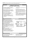
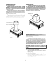
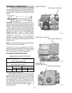
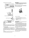
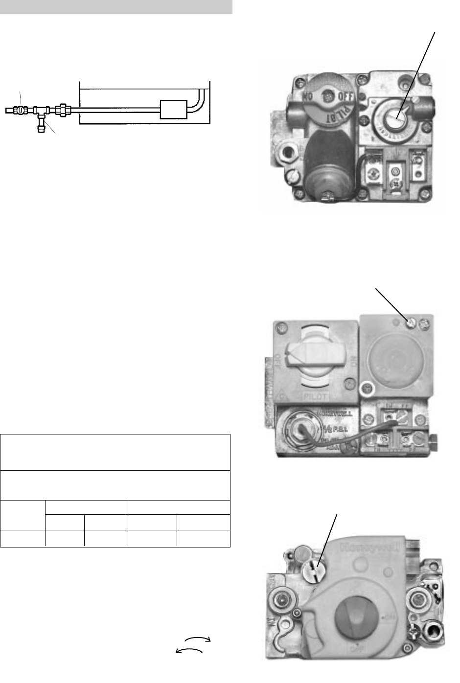
GAS PRESSURE REGULATOR
The gas pressure regulator is preset and sealed at
4" W.C. for natural gas, and ll" W. C. for propane gas.
Between the gas valve and the burners is a l/8" pipe
plug. The pressure at this point, taken with a manome-
ter, should be about 3.7" W. C. natural gas and l0.5"
W.C. propane gas. If an adjustment is needed, remove
seal and turn adjustment screw clockwise to
increase pressure or counter-clockwise to
decrease pressure.
PIPE SIZING FOR GAS CONNECTIONS
MAXIMUM EQUIVALENT PIPE LENGTH
Natural Gas 1000 BTU/ FT . 60 Specific Gravity
@ 0.5" WC Pressure Drop
Propane Gas 2500 BTU/ FT l.53 Specific Gravity
@ 0.5" WC Pressure Drop
1/2" 3/4"
MODEL N P N P
105B 25 55 95 200
3
3
Manual Shut Off
Valve
Sediment Trap
Fig. # 8156.1
ROBERTSHAW MV
Gas Pressure Adjustment
Fig. # 9263
HONEYWELL VALVE MV
Gas Pressure Adjustment
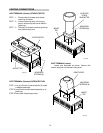
HONEYWELL IID
VR 8300 GAS VALVE
Gas Pressure Adjustment
Fig. # 9265
12
Fig. # 9264