


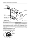
ELECTRICAL WIRING
NOTE:
If it is necessary to replace any of the original
wiring, it must be replaced with 105
°
C wire or its
equivalent, except all black wire must be replaced with
150
°
C wire or its equivalent.
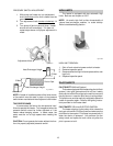
MILLIVOLT SYSTEM
The
Millivolt System Residential Heater
is equipped
with a self-generating electrical system in which the
electric current is provided by means of a pilot generator.
No external electrical connections are required.
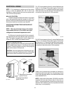
ELECTRONIC INTERMITTENT IGNITION DEVICE
SYSTEM (IID)
NOTE:
When the electrical hookup to the heater
requires both 24V and 115V or 240V, each input
voltage must be isolated in separate conduit.
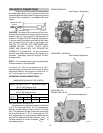
The
Electronic Intermittent Ignition Device
automati-
cally lights the pilot and main burners upon a call for the
heat. The heater is supplied with a dual voltage trans-
former for 120V or 240V input power hookup.
NOTE:
IID Propane Units Only
Heater is equipped with an electronic ignition device with
a 100% safety lockout feature. If the heater fails to start
or lockout. Reset the ignition device by interrupting the
power to the heater for 60 seconds.
CAUTION:
If service replacement of the electronic igni-
tion device is required. Replace only with a 100% safety
lockout device with 90 second trial for pilot ignition.
14
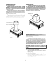
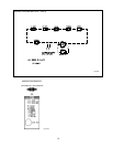
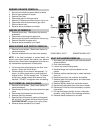
Fig. # 8929.1
Robertshaw Intermittent
Ignition Device
Honeywell Intermittent
Ignition Device
Fig. # 8085
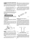
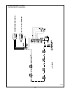
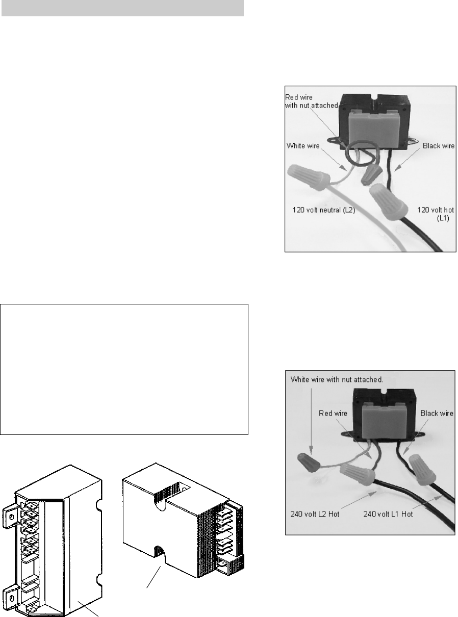
For 120 V input power to the unit, connect the black wire
to the “L1” or hot leg of the power supply. Connect the
white wire to the “L2” or neutral leg of the power supply.
Attach the wire nut to the red wire. There should be no
connection to the red wire for 120V operation.
Fig. #9240
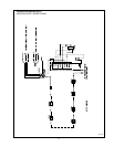
For 240 V input power to the unit, connect the black wire
to the “L1” or hot leg of the power supply. Connect the
red wire to the “L2” or second hot leg of the power supply.
Attach the wire nut to the white wire. There should be no
connection to the white wire for 240V operation.
Fig. # 9241
Heater must be electrically grounded and bonded in
accordance with local codes, or, in the absence of local
codes, with the latest edition of the National Electrical
code, ANSI/NFPA 70.
NOTE: Input power to the heater (120/240V) should be
supplied from the load (Pump) side of time clock or
switch. Connecting heater to continuous power source
will allow "Fail" indications (service and pressure switch)
when pump is not operating.