


200-2341 31
In some areas of the United States, a USDA Forest
Service approved exhaust spark arrestor is legally
required. This optional accessory is added to the
generator during initial installation. To identify whether
the generator is equipped with a spark arrestor, inspect
the exhaust tailpipe opening for a screen. If a screen is
present in the tailpipe, the spark arrestor option is
installed.
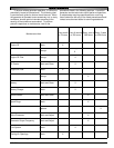
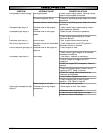
Spark arrestors require periodic inspection and
cleaning as indicated in the recommended service
interval table on page 25. To maintain the spark
arrestor, the following steps are recommended.
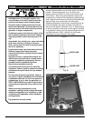
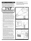
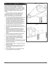
1. To gain access to the spark arrestor assembly inside
the exhaust chamber, some disassembly of the
generator cabinet is required. Begin the disassembly
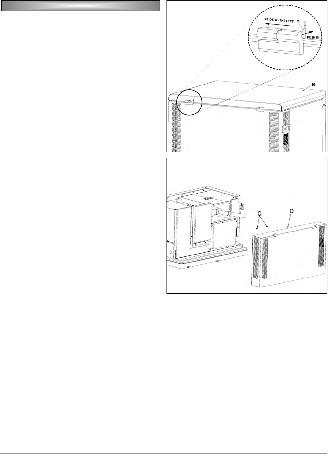
by carefully removing the lid from the enclosure.
First push in the hinge retaining stop (A), then slide
the lid (B) to the left to free it from the rest of the
enclosure as shown in Fig GG. Set the lid aside on a
soft surface to avoid scratching the lid paint.
2. Open the battery access panel by removing the 3
screws and rotating the panel outward (see Fig. E on
page 28).
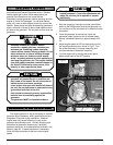
3. Remove the 2 screws (C) fastening the exhaust
chamber panel (D) to the rear engine firewall (see
Fig HH). Slide the exhaust chamber panel (D)
upward to free it from the enclosure and carefully set
it aside.
4. Remove the spark arrestor assembly by loosening
the screw holding the arrestor to the muffler.
5. Use a low pressure stream of compressed air or
water to blow particles from the spark arrestor
screen. Ensure that all particles are completely
flushed from the tailpipe.
6. Visually inspect the spark arrestor screen to for holes
or breaks in the screen. If any are found, replace the
spark arrestor assembly.
7. Reinstall the spark arrestor on the muffler outlet and
replace the clamp.
8. Slide the exhaust chamber panel (D) back into place
and install the screws (C) holding it to the rear
engine firewall.
9. Slide the lid (B) back onto the hinges and reinstall
the retaining clip to secure the lid place.
SS
SS
PP
PP
AA
AA
RR
RR
KK
KK
AA
AA
RR
RR
RR
RR
EE
EE
SS
SS
TT
TT
OO
OO
RR
RR
CC
CC
LL
LL
EE
EE
AA
AA
NN
NN
II
II
NN
NN
GG
GG
Fig. GG
Fig. HH