


14 200-2341
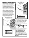
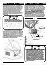
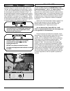
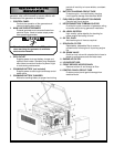
After electrical connections are complete, the next
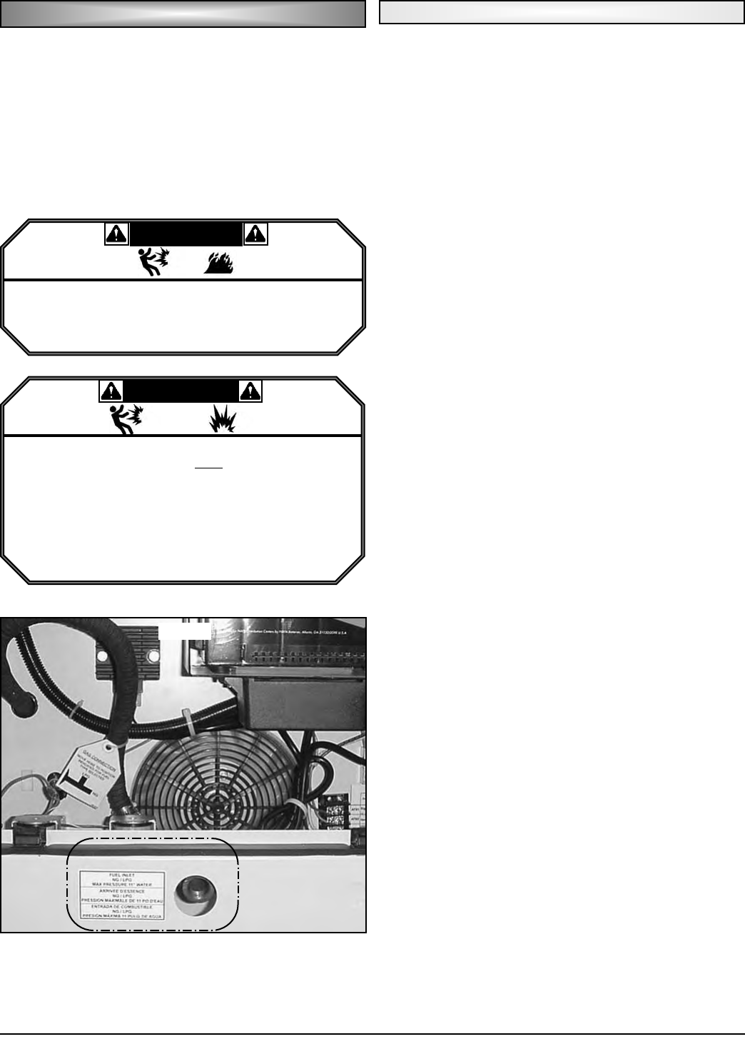
installation step is to connect a fuel supply to the unit.
The fuel inlet fitting supplied with the generator is male
½" NPT and is located adjacent to a fuel access hole in
the lower engine end panel as illustrated in Fig E. To
accommodate potential settling of the generator relative
to rigid supply pipeline, use of a flexible line to make the
final connection in the supply line is suggested. When
making flexible connections, use only materials rated for
the fuel supplied and approved for use by local, regional
or national codes and/or regulatory agencies.
When supplying natural gas as the operating fuel,
provide fuel with a minimum of 1000 BTU/ft
3
at inlet
pressures between 7" and 11" of water column (4 - 6
oz). Failure to meet these minimums will cause the
generator to run poorly and/or may limit output to values
below nameplate value. If fuel with these qualities is not
available, a low calorific fuel system kit may be required,
at additional cost. Contact the customer service center
to determine if a kit is required in cases of inadequate
fuel quality.
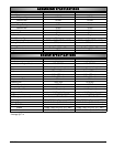
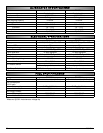
Refer to the Fuel Consumption Table on page 13 for
fuel flow requirements for the unit installed. Size all
feeding piping to deliver sufficient flow above the
minimum pressure of 7" water column (4 oz).
Per the National Gas Code (NFPA 54 - ANSI
2223.1), a manual shutoff valve in the fuel supply line
to the generator is recommended.
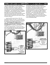
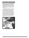
Once all external connections are complete, check
the position of the flexible engine supply hose, as shown
in Fig F. When configuring a generator to run on a
specific fuel, it is necessary to verify correct positioning
of the hose on the fuel pressure regulator outlet. The
factory default position is for natural gas (NG), as
indicated in Fig F. If the fuel hose is not in the proper
position, move it to the tee branch labeled NG, making
sure the brass cap is placed securely on the opposite
branch. With fuel supply attached and the flexible engine
supply hose on the proper branch of the regulator output,
the fuel hookup is complete. The generator is supplied
with a fixed orifice tuned to provide proper fuel flow and
no further adjustment of the fuel system is possible or
required.
FF
FF
UU
UU
EE
EE
LL
LL
HH
HH
OO
OO
OO
OO
KK
KK
UU
UU
PP
PP
Natural Gas (NG)
FIG. E
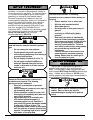
DDAANNGGEERR
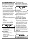
• All fuel system installations MUST BE done by a
licensed plumber or licensed gas technician
and must comply with all applicable codes,
standards and regulations.
WWAARRNNIINNGG
• Natural Gas and Propane Vapor are highly
explosive gases. Check ALL fuel system
connections for leaks before starting
engine/generator set.
• DO NOT use a flame to check for leaks.
• Use approved equipment and methods to check
for leaks.