


10 200-2341
Once the generator is anchored in its final position, it
is ready for electrical connections. The generator is
supplied with two terminal blocks for connection of three
distinct electrical circuits; main line output power, GFCI
power input and remote start signal. Main line output
power is the electrical output of the generator, GFCI
input powers the battery charger and optional block
heater devices and the remote start signal is the
interface with an Automatic Transfer Switch that allows
the generator to operate automatically upon a utility
power outage.
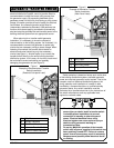
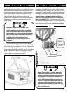
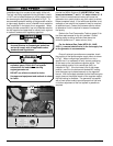
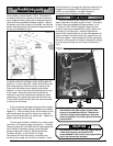
To access the wiring connection terminal blocks,
open the generator lid (A) and place the lid prop rod (B)
into the slot (C) on the underside of the lid. Remove the
three screws (D) from the access panel, then open the
hinged access panel (E) as shown in Fig A. The access
panel is removable by pulling the pins from the panel
hinges. Locate the two terminal blocks (F) on the lower
right corner of the engine partition panel.
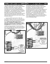
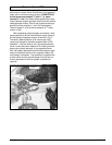
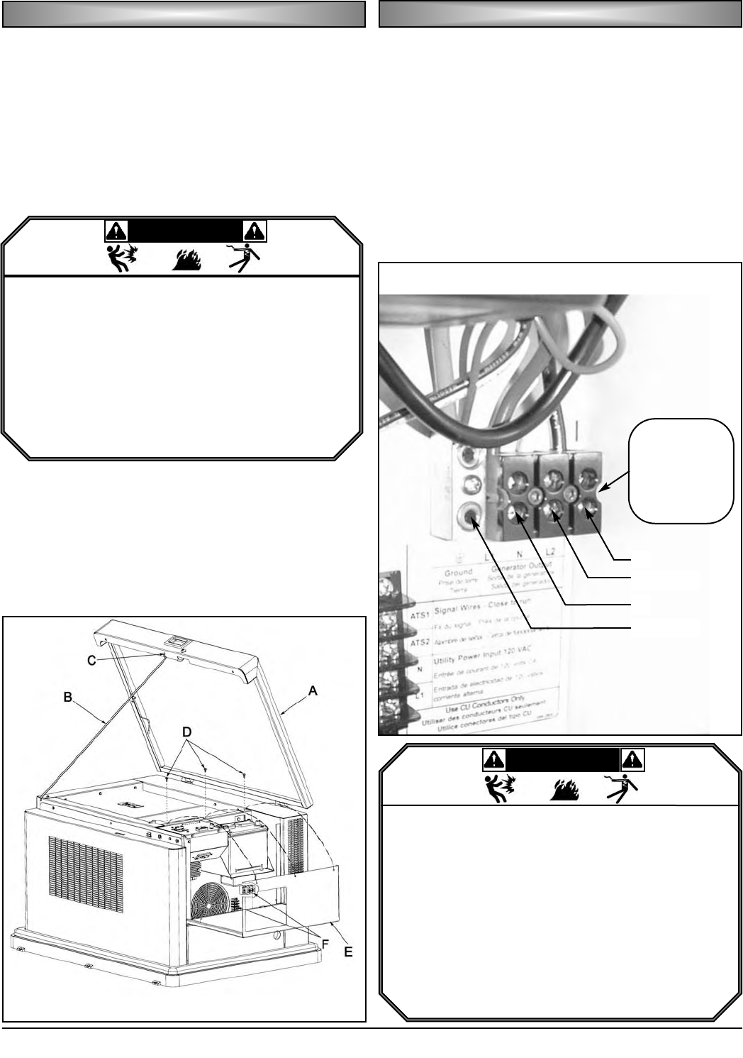
The output circuit of the generator is 4-wire, 240V,
rated for the amperage as shown on the generator
nameplate. Connection to the transfer switch requires
two leads, commonly referred to as "hot" leads (L1 & L2),
a neutral (N), and ground lead. Positions of these leads
are labeled on the main line output terminal block, also
shown in Fig. B. Select proper power output wire
sizes according to allowable ampacities given in
Table 310-16 of the latest revision of The National
Electric Code(NFPA 70). To connect the wires, strip
the insulation back approximately ½" from the end of the
wire, insert the stripped end into the terminal block, then
torque the terminal block screw to 35 in-lbs (4.0 N-m).
EE
EE
LL
LL
EE
EE
CC
CC
TT
TT
RR
RR
II
II
CC
CC
AA
AA
LL
LL
HH
HH
OO
OO
OO
OO
KK
KK
UU
UU
PP
PP
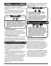
DDAANNGGEERR
• Improper installation can damage your
electrical system and cause property damage,
serious personal injury or death. Installation
MUST be performed by a licensed electrician
and plumber, or gas technician and installation
MUST comply with all applicable building and
electrical codes. Some areas may require
building permits and/or detailed sight
inspections prior to approving the unit for
operation.
MM
MM
AA
AA
II
II
NN
NN
LL
LL
II
II
NN
NN
EE
EE
OO
OO
UU
UU
TT
TT
PP
PP
UU
UU
TT
TT
PP
PP
OO
OO
WW
WW
EE
EE
RR
RR
FIG. A
FIG. B
L2
NEUTRAL
L1
GROUND
MAIN
LINE OUTPUT
(CONNECT TO
AUTOMATIC
TRANSFER
SWITCH)
DDAANNGGEERR
• Hazardous voltage can cause severe injury or
death. Electrocution is possible whenever
electricity is present. Open the main circuit
breaker of all power sources before servicing
the equipment. Configure the installation to
electrically ground the generator set, transfer
switch and related equipment and electrical
circuits to comply with applicable codes and
standards. Never contact electrical leads or
appliances when standing in water or on wet
ground because these conditions increase the
risk of electrocution.