


22 200-2341
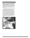
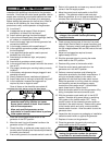
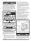
A standby generator is an engine driven air cooled
system to convert the energy contained in either liquid
propane vapor or natural gas to electrical power. When
coupled with an automatic transfer switch to monitor for
failure of utility power, the unattended system can start,
stop and transfer between sources to insure a nearly
seamless supply of power. The generator is housed in a
weather resistant, sound attenuated enclosure for
outdoor installation only.
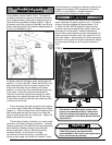
Before installing and starting the generator, become
familiar with the controls and operational features of the
generator. Know how the control panel operates, what to
expect when activating control panel switches and how
to shut the generator off in the event of an emergency.
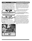
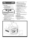
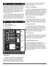
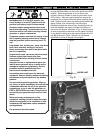
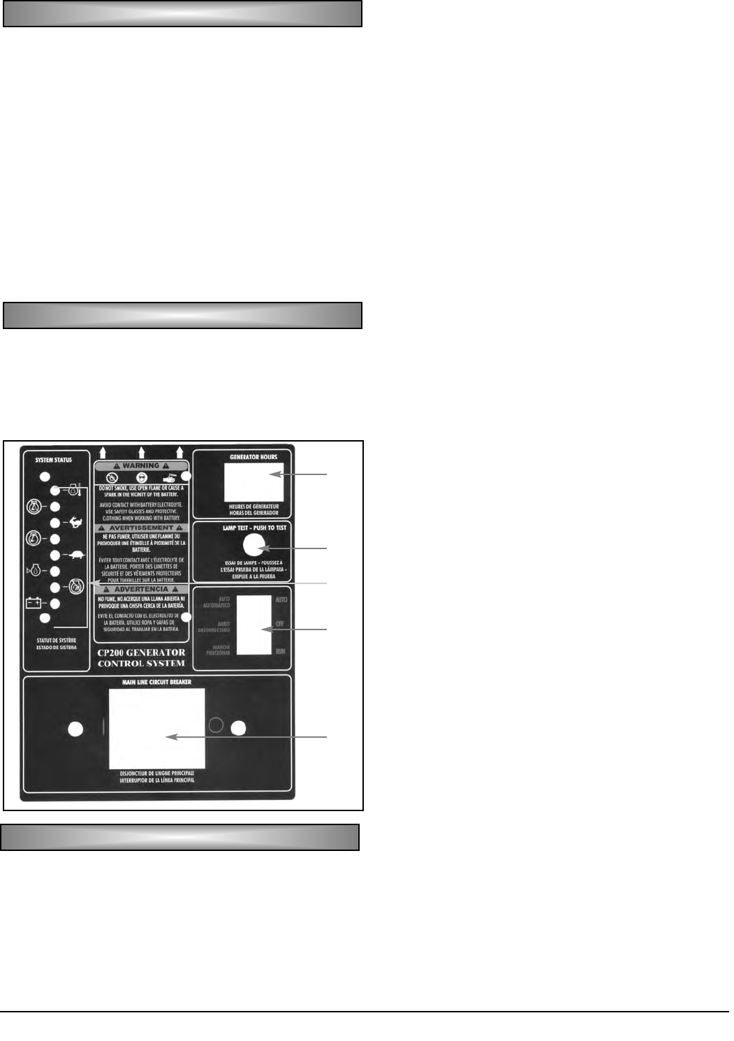
A. MODE SWITCH
B. CIRCUIT BREAKER
C. STATUS INDICATOR LIGHTS
D. HOUR METER
E. LAMP TEST SWITCH
A. Mode Switch
The Mode switch is used to set the operating state of
the generator. Placing the switch in the OFF position
prevents engine operation or stops the engine if it is
already running. Moving the switch to the RUN position
immediately starts the generator. Putting the switch in
the AUTO position sets the generator for unattended
operation under the control of properly matched
automatic transfer switch.
B. Main Line Circuit Breaker
A Main Line Circuit Breaker is provided to protect the
generator from damage caused by electrical faults within
the attached electrical distribution system. It is also used
to isolate the output of the generator from the connected
electrical distribution system by moving the breaker
handle to the OFF position. Placing the breaker in this
position does not prevent startup of the generator.
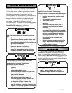
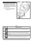
C. Status Indicator Lights
Status indicator lights are provided to communicate
the status of the generator to the user. Under normal
running conditions, only the green Generator On light is
lit. Function of all other lights are described on page 24.
D. Generator Hour Meter
The Generator Hour Meter is provided to track the
total numbers of hours of operation. The hour meter
runs whenever the engine is running and the alternator is
producing electricity. Placing the main line circuit
breaker in the OFF position while the engine is running
does not stop the meter from counting hours.
E. Lamp Test Switch
A lamp test switch is provided to check for function of
all indicator lights. Press the lamp test switch while the
engine is at rest, with the control panel mode switch in
the OFF position to illuminate all status lights.
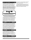
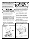
F. Engine Charging Circuit Fuse
The Engine Charging Circuit Fuse provides
protection to the engine mounted alternator in the event
of electrical faults in the positive (+) battery circuit.
Failure of this fuse prevents charge from reaching the
battery when the generator is running, leading to early
battery failure. Replace the fuse only with an equivalent
size and style of fuse to prevent damage to the generator
electrical control system.
GG
GG
EE
EE
NN
NN
EE
EE
RR
RR
AA
AA
TT
TT
OO
OO
RR
RR
OO
OO
PP
PP
EE
EE
RR
RR
AA
AA
TT
TT
II
II
OO
OO
NN
NN
CC
CC
OO
OO
NN
NN
TT
TT
RR
RR
OO
OO
LL
LL
PP
PP
AA
AA
NN
NN
EE
EE
LL
LL
FF
FF
EE
EE
AA
AA
TT
TT
UU
UU
RR
RR
EE
EE
SS
SS
C
D
E
A
B
CC
CC
OO
OO
NN
NN
TT
TT
RR
RR
OO
OO
LL
LL
PP
PP
AA
AA
NN
NN
EE
EE
LL
LL
SS
SS
WW
WW
II
II
TT
TT
CC
CC
HH
HH
EE
EE
SS
SS