


200-2341 11
A ground fault circuit interrupting (GFCI) receptacle
is provided with the generator to power the battery
charger for reliable starting. It is also intended to power
an optional block heater if that option is desired.
Connection of this circuit to a power supply that is
only present when normal utility power is supplied is
recommended. By connecting the GFCI in this fashion,
it is possible to insure that neither the battery charger or
block heater are on while the engine is running.
Precautions are engineered into the generator to prevent
these occurances but connection of the circuit in this
fashion provides an additional fail-safe method of engine
and battery protection.
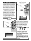
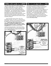
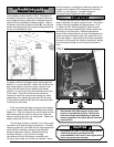
Input to the GFCI circuit is 3-wire, 120V, 15A.
Connections include a "hot" lead (L1), neutral (N) and
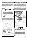
ground lead. Positions of the incoming wire connections
are labeled at the auxiliary connection block, shown in
Fig.C. Select proper GFCI supply wire size
according to allowable ampacities given in Table
310-16 of the latest revision of The National Electric
Code(NFPA 70). To connect the wires, strip the
insulation back approximately ¼" from the end of the
wire, insert the stripped end under the screw and washer
on the terminal block, then torque the terminal block
screw to 20 in-lbs (2.3 N-m).
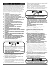
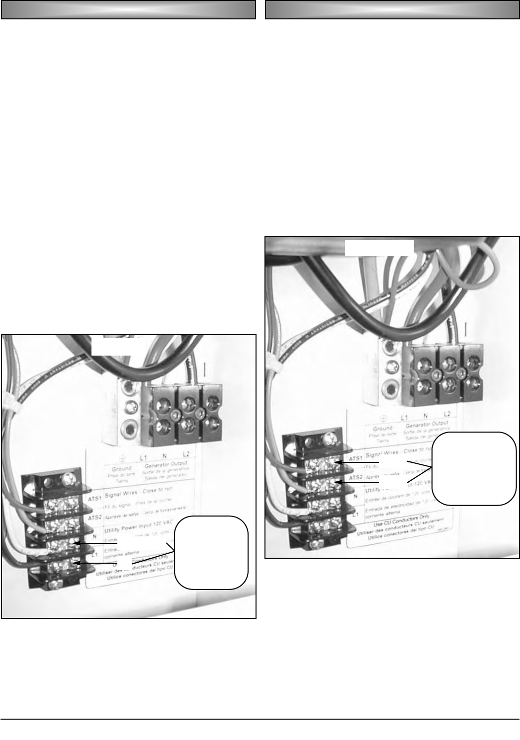
When the control panel mode switch is placed in the
AUTO position, generator starting and stopping is
controlled by the opening or closing of a set of voltage
free contacts. Two wires from those contacts are
connected to the generator through the auxiliary
connection block shown in Fig. D. Use of a twisted pair of
stranded copper wire no smaller than AWG 18 gage is
recommended. To insure proper operation of the auto
start feature, use a transfer switch offering “close-to-run
control contacts. To connect the wires, strip the
insulation back approximately ¼" from the end of the
wire, insert the stripped end under the screw and washer
on the terminal block, then torque the terminal block
screw to 20 in-lbs (2.3 N-m).
GG
GG
EE
EE
NN
NN
EE
EE
RR
RR
AA
AA
TT
TT
OO
OO
RR
RR
SS
SS
TT
TT
AA
AA
RR
RR
TT
TT
SS
SS
II
II
GG
GG
NN
NN
AA
AA
LL
LL
FIG. C
GG
GG
FF
FF
CC
CC
II
II
CC
CC
II
II
RR
RR
CC
CC
UU
UU
II
II
TT
TT
SS
SS
UU
UU
PP
PP
PP
PP
LL
LL
YY
YY
FIG. D
NEUTRAL
L1
GFCI
CIRCUIT
SUPPLY
(CONNECT TO
120V UTILITY
POWER)
ATS1
ATS2
GENERATOR
START SIGNAL
(CONNECT TO
AUTOMATIC
TRANSFER
SWITCH)