


200-2341 17
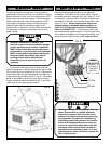
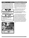
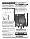
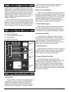
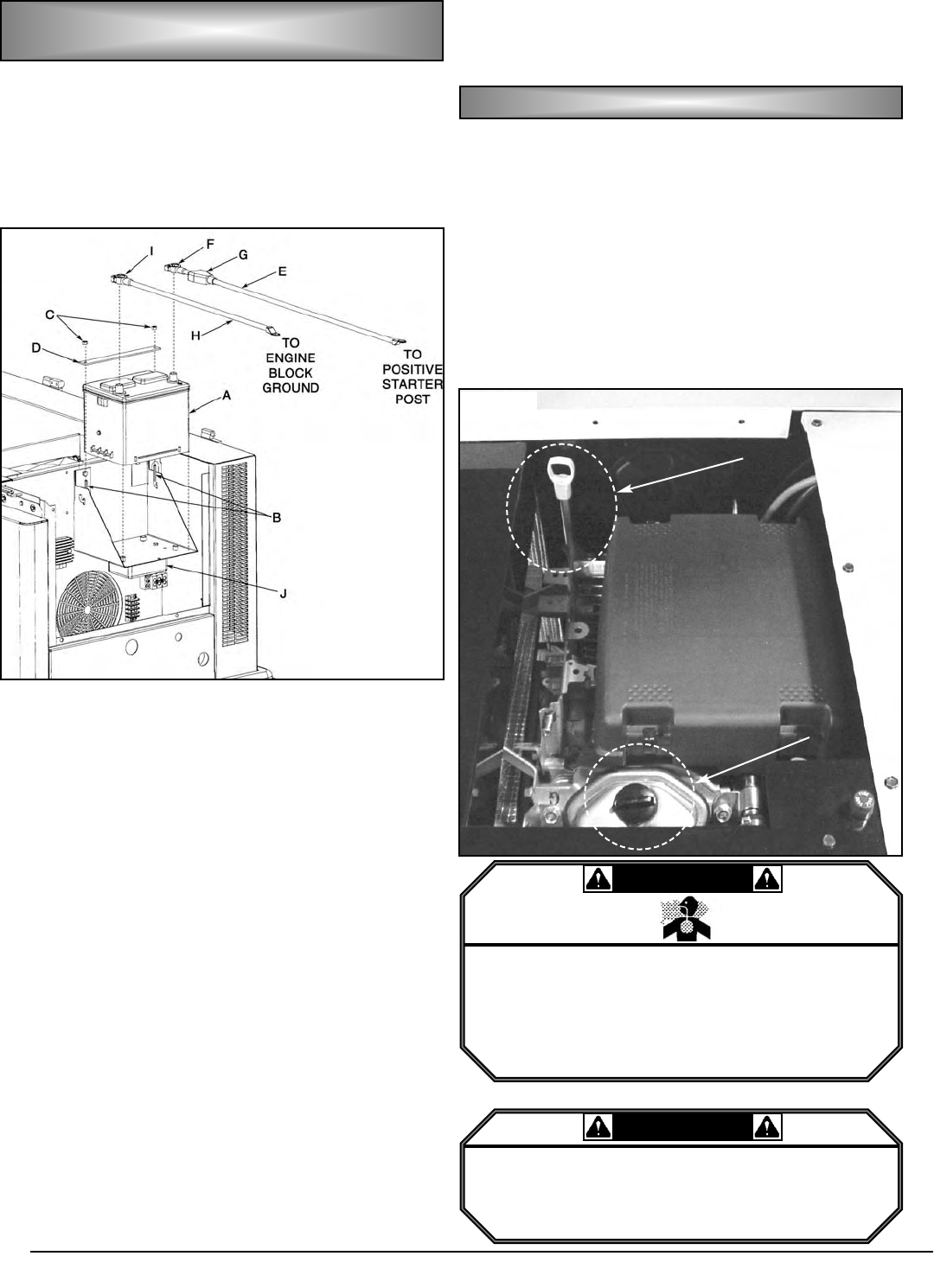
To install the battery, begin by placing the battery (A)
into the battery rack as shown in Fig G. Orientation of
the battery terminals is according to installer preference
as the supplied battery cables are of adequate length to
reach terminals regardless of battery direction. Secure
the battery to the rack using the J-bolts (B), nuts (C) and
battery strap (D) packed in the literature bag packed with
the unit, as illustrated by Fig G.
After the battery is tight in the rack, begin attaching
the battery cables to the battery posts, starting with the
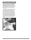
positive (+), or red, cable (E). Loosen the bolt (F) on the
post clamp slightly to allow the clamp to expand, then
firmly push the clamp onto the battery post marked
positive (+) until the top of the post extends past the top
of the clamp. Rotate the clamp around the post as
required to insure the clamp cannot contact any metal
components, then tighten the clamp bolt (F) until snug.
Finally,slide the post boot (G) down the cable and place
it entirely over the clamp.
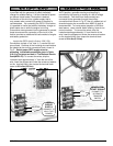
Finish connecting the battery by placing the negative
(-), or black, battery cable (H) to the battery post marked
negative (-). Push the clamp firmly over the post until the
post extends past the top of the clamp, then rotate the
clamp to avoid contact with any metal parts. Tighten the
battery clamp bolt (I) until snug.
The final step of battery installation is to verify proper
connection of all battery charger connections. A battery
charging system (J) is included with the engine/generator
set to maintain the battery charge during extended
periods of generator inactivity, therefore providing
consistent starting. A quick check of charger
connections will verify that factory connections are
correct so the charger can function as intended. Insure
that the charger is connected by checking to see that it is
plugged into a powered GFCI receptacle, and that the
positive (+) and negative (-) charger cables are
connected to their respective battery cables.
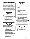
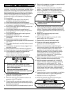
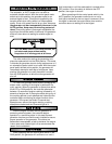
Once all connections are made, the final installation
step is verification of proper engine oil level. The engine
is factory filled and shipped with approximately 1.5 qt
(1.4 liters) of SAE 10W-30 weight oil. Begin the level
check by removing the dipstick (K), wiping it clean, then
reinserting it into the engine. Remove the dipstick a
second time, checking that the oil level falls between the
upper and lower limit marks (see Fig A ,page 26) on the
end of the dipstick. Adjust engine oil level as required so
the level is at the upper limit mark on the dipstick, adding
oil to the engine through the oil fill cap (L) as shown in
Fig H.
BB
BB
AA
AA
TT
TT
TT
TT
EE
EE
RR
RR
YY
YY
PP
PP
LL
LL
AA
AA
CC
CC
EE
EE
MM
MM
EE
EE
NN
NN
TT
TT
AA
AA
NN
NN
DD
DD
CC
CC
OO
OO
NN
NN
NN
NN
EE
EE
CC
C
C
TT
TT
II
II
OO
OO
NN
NN
((
((
cc
cc
oo
oo
nn
nn
tt
tt
..
..
))
))
LL
LL
UU
UU
BB
BB
RR
RR
II
II
CC
CC
AA
AA
TT
TT
II
II
OO
OO
NN
NN
FIG. G
FIG. H
• State and federal agencies have determined
that contact with used engine oil can cause
cancer or reproductive toxicity. Take care to
limit skin contact and breathing of vapors as
much as possible. Use rubber gloves and wash
exposed skin.
WWAARRNNIINNGG
• Any attempt to crank or start the engine before
it has been properly serviced with the
recommended oil will result in an engine failure
that is not covered by warranty.
CCAAUUTTIIOONN
L
K