


10
ASSEMBLY
WARNING: If received assembled,
review allassembly steps to ensure your unit
is properly assembled and all fasteners are
secure.
Examine parts for damage. Do not use dam-
aged parts.
NOTE: If you need assistance or find parts
missing or dam aged, call 1-800 -554-6723.
TOOLS REQUIRED
S Hex wrench
S Chain adjustment tool (bar tool)
INSTALLING PRUNER OR LINE
TRIMMER ATTACHMENT
CAUTION:
When removing or installingat-
tachments, placethe uniton a flatsurface for
stability.
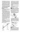
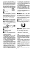
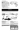
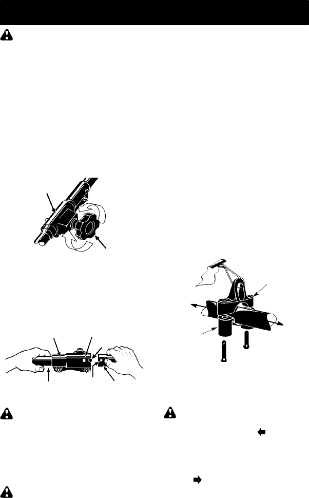
1. Loosen the coupler by turning the knob
counterclockwise.
Coupler
Knob
LOOSEN
TIGHTEN
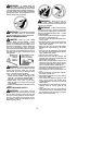
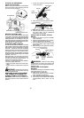
2. Remove theshaft capfrom attachment(if
present).
3. Position locking/release button of attach-
ment into guide recess of coupler.
4. Push theattachmentintothe coupleruntil
the locking/release button snaps into the
primary hole.
5. Beforeusing theunit,tightenthe knobse-
curely by turning clockwise.
Coupler Primary Hole
Upper
Shaft
Locking/
Release
Button
Lower
Attachment
Guide R ecess
WARNING: Make sure the locking/
release button is locked in the primary hole
andthe knob issecurely tightenedbefore op -
eratingtheunit. Allattachmentsaredesigned
to be used in the primary hole.
For optional attac hm ents, see the AS-
SEMBLY section of the applicable attach-
ment instruction manual.
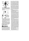
SHOULDER STRAP ASSEMBLY
WARNING: Proper shoulder strap
adjustments must be made with the motor
completely stopped before using unit.
1. Tryonshoulderstrapandadjustforfitand
balance before starting the unit or begin-
ning a cutting operation.
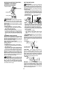
2. Insertyourrightarmandheadthroughthe
shoulder strap and allowit to rest onyour
left shoulder. Make sure the danger sign
is centered on your back andthe hoo k is
to the right side of your waist.
NOTE: A one-half twist is built in the shoul-
der strap to allow the strap to rest flat on the
shoulder.
3. Adjust the strap, allowing the hook to be
about 3 -- 6 inches (8 -- 15 cm) below the
wai st.
4. Fasten the strap hook t o the clamp lo-
cated between the trigger handle and the
assisthandleandliftthetooltotheoperat-
ing position.
NOTE: It may be necessary to relocate the
shoulder strap clamp on the shaft for proper
balancing of unit.
TO RELOCATE SHOULDER STRAP
CLAMP:
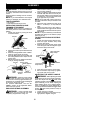
1. Loosen and r emove both clamp screws.
2. Place the upper shou lder strap clamp
over the upper shaft.
3. Position the lower shoulder strap clamp
under theupper shaft and align theupper
and lower clamp screw holes.
Upper Shoulde r
Strap Clamp
Screws
Lower Shoulder
Strap Clamp
POWERHEAD
END
ATTACHMENT
END
4. Insert two screws into the screw holes.
5. Secure shoulder strap clamp by tighten-
ing screws with a hex wrench.
ADJUSTING T HE ASSIST HANDLE
WARNING: When adjusting the assist
handle duringpruner use, besureit remainsbe-
tween the coupler and the
lower arrow
(closest tocoupler) onthe safety label toensure
proper balancing of unit. When adjusting the
assist handle during u se of optional attach-
ments (or handlebar f or edger attachment), it
must berepositioned between thetrigger switch
and the
upper arrow (closest to motor) on
the saf ety l abel.
1. Loosen wing nut on handle.
2. Rotate the handle on the shaft to an up-
right position; retighten wing nut.