


P/N 472128 Rev. E 11-5-07
16
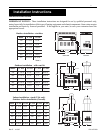
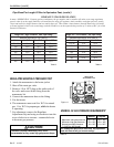
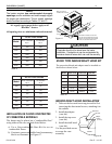
SHEET
METAL
BLOCKS
HOLLOW MASONARY BLOCKS, NOT LESS THAN
4" THICK (LAID WITH ENDS UNSEALED AND JOINTS
MATCHED FOR AIR CIRCULATION). COVER BLOCKS
WITH 24 GA. (MIN.) GALVANIZED SHEET METAL.
H
I
G
H
P
E
R
F
O
R
M
A
N
C
E
H
E
A
T
E
R
6" Min.
6
" M
in
.
TM
BASE FOR USE ON
COMBUSTIBLE FLOORS
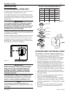
H
O
T
S
P
A
T
E
M
P
H
O
T
P
O
O
L
T
E
M
P
C
O
L
D
O
F
F
S
PA
P
O
O
L
T
H
E
R
M
O
S
T
A
T
S
E
L
E
C
T
H
O
T
C
O
L
D
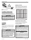
edistuOmorFriAllA
ledoM
noitsubmoCrofriA
.nI.qS
noitalitneVriA
.nI.qS
0517373
0020505
0523636
0037777
0530909
004001001
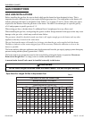
Table 13.
Table 12.
ledoMdooHtfarD.oNtcudorP.aiDtneV
05151HD722064.ni6
00202HD822064.ni7
05252HD032064.ni7
00303HD132064.ni8
05353HD332064.ni9
00404HD432064.ni01
Table 14.
edisnImorFriAllA
ledoM
noitsubmoCrofriA
.nI.qS
noitalitneVriA
.nI.qS
051051051
002002002
052052052
003003003
053053053
004004004
Figure 17.
CAUTION
Chemicals should not be stored near the heater
installation. Combustion air can be contaminated by
corrosive chemical fumes which can void the warranty.
NOTE
The heater requires two uninterrupted air supply
openings; one for ventilation and one to supply oxygen
for proper gas combustion. The air supply openings
should be sized according to Tables 12. and 13.
Air supply requirements below apply to all
MiniMax
®
heaters
All opening sizes are minimum and unobstructed.
I
NSTALLATION ON FLOORS CONSTRUCTED
OF COMBUSTIBLE MATERIALS
The heater may be placed on a “combustible floor”
using either of the two methods listed below:
a) Use a Non-combustible Base Kit for use on
combustible floors.
b) Construct a non-combustible base from masonry
blocks as illustrated, see Figure 17.
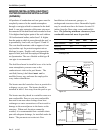
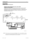
Installation (contd.)
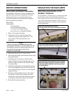
STACK TYPE INDOOR DRAFT HOOD KIT
The proper draft hood and adapter must be installed on
the heater as shown below:
Screw
(2 PLC's)
HEATER
Top Cover
Adaptor
Draft Hood
INDOOR DRAFT HOOD INSTALLATION
1. Take out the louvered outer top piece after first
removing the sheet metal screws, attaching it to
the cabinet.
2. Install the adaptor
(vent kit).
3. Install the top cover
(vent kit).
4. Install the draft hood
(vent kit).
Use the provided screws
to secure the vent
assembly.
Figure 18.