


Rev. E 11-5-07 P/N 472128
11
WATER CONNECTIONS
Reversible Inlet/Outlet Connection
The MiniMax
®
CH heater is factory assembled with
right side inlet/outlet water connections. The inlet/
outlet header can be reversed for left side water
connections without removing the heat exchanger.
Reversing Water Connections
Disassembly
Tools needed:
1/4 in Nut Driver
9/16 in. Socket and Wrench
1/2 in. & 9/16 in. Open Wrench
Screw Driver(s) - (Flathead & Phillips)
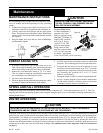
1. Remove the inspection plates.
2. Disconnect all wires from the high-limit
switches except the short jumper wire. The
exact order of the disconnection is not
important.
NOTE
There is no reason to remove the high-limit
and pressure switches or the thermister from the
front header during the reversing procedure, as
they will be in the proper location when
installed on the left side.
3. Disconnect the pressure switch wiring.
4. Disconnect the thermostat thermister leads from
the control board.
5. Exchange the in/out header with the return
header. Replace the heat exchanger tube seals
with new seals provided in the Quick-Flange
Accessory Bag.
6. Install the temperature sensing bulb by passing
the wires through the hole provided on the left
side of the brace panel. Route wires through the
support bracket.
7. Reconnect all the high limit wires. Reconnect
the pressure switch wiring. Route the wires
through the same hole as the thermostat sensor
wires and reconnect thermister to the board.
8. Reinstall the inspection plates.
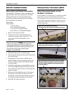
Installation (contd.)
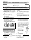
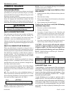
INSULATING THE HIGH LIMITS
When Reversing Heads on the
MiniMax
®
CH Heater
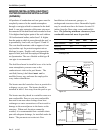
On the MiniMax
®
CH heater there is insulation installed
by the factory on the return head side of the heaters.
This insulation is there so that if the heads are reversed
in the field, during initial installation of the heater, the
reflected heat from the flue collector will be insulated
from the high limits.
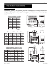
Return head in position before removal.
This view shows the insulation installed by the factory.
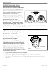
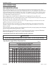
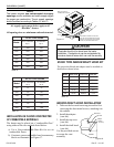
Return head removed and new tube seals installed. Now
ready to accept the installation of the main head.
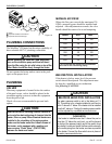
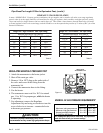
Lift the installation to allow the main head to be installed.
When head is placed into position, release the insulation;
it will now shield the high limits from the heat produced
by the flue collector.