


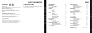

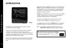


Overview
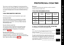
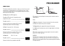
CYCLE-TIME
The choice of cycle-time is influenced by the external switching
device or load. e.g. contactor, SSR, Valve. A setting that is too long
for the process will cause oscillation and a setting that is too short
will cause unnecessary wear to an electro-mechanical switching
device.
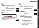
Cycle-time selection methods
The following methods of cycle-time selection may be used:
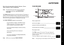
Autotune calculated
After Autotune has been run and completed the calculated cycle-
time can be manually accepted or adjusted to suit the switching
device. For selection method see Select Autotune Calculated
Cycle-time.
Pre-select autotune cycle-time
The controller can be programmed to automatically accept the
calculated Autotune cycle-time. For selection method see Pre-
Select Automatic Acceptance of Any Autotune Cycle-time.
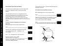
Pre-select before autotune
The controller can be programmed manually with any cycle-time
between 0.1 and 81 sec. This cycle-time will not be changed by any
Autotune functions. For selection method see Pre-Select Cycle-
time Before Autotune.
Factory set
To use the 20 sec factory set cycle-time no action is needed
whether Autotune is used or not.
Further information can be programmed into the controller, see
SECOND SETPOINT, RANGING AND SETPOINT LOCK, IMPROVING
CONTROL ACCURACY
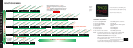
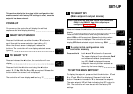
Functions and options
The facilities of the controller are selected from the multi-level menu
using the front panel mounted buttons.
Note: It is advisable to study this section before any
programming is undertaken.
Each level within the multi-level menu offers different functions, see
FUNCTIONS MENU for menu of main functions. Each function has a
range of user selections or options, see FUNCTION LIST for
functions and options details.
The controller has two modes, program mode and operating mode.
When in program mode the controller can be programmed with
settings and functions to suit the application. When in operating
mode the controller uses the setting and functions entered in the
program mode to control the application and also displays both the
process variable and setpoint temperatures. For full details on how
to program the controller see VIEWING AND SELECTING
FUNCTIONS.
Note: In this manual the letter k is represented by the
character
K
4