


Advanced Settings
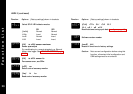
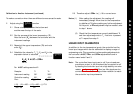
3 Allocate the output devices at function
as described in
SET-UP
, enter the configuration
into the memory and proceed as follows:
Calculate the values for the controller settings
for and using the example below
as a guide:
4 to 7mV input from transducer is required to
display 0 - 110 units
Chose Linear Range Lin4 4-20mV = 0 to 1000 units.
HI.SC = Nominal Signal Span x required span
actual signal span
(20-4) x (110-0) = 587
(7-4)
SPAN = (
hi.SC
- nominal scale span) x
hi.SC
Nominal Scale Span
(587-1000) x 587 = -242
1000
These settings should provide the correct scaling adjustment, but a
value for
ZEro
may need to be established by applying the lowest
and highest mV input signal and recording the display offset. Check
that this is the same at each end, and enter this plus or minus value
as a
ZEro
adjustment. Should there be a difference between the
two readings, a further adjustment of the
SPAn
setting can be made.
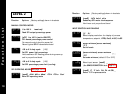
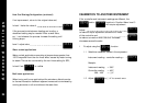
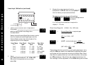
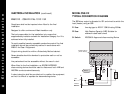
1 Power up the controller, and in response to
the prompt
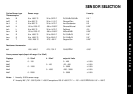
select an appropriate Linear Range from
the table below.
Ensure that the Nominal Signal Span chosen is wider
than the transducer’s actual signal span, and the
Nominal Scale is wider than the full scale of the
engineering units to be displayed.
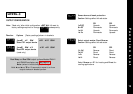
2 Select
then select the process unit,
°C
,
°F
,
Bar
,
PSI
,
Ph
, or
rh
. If the required unit is not shown
select
Set
.
Linear Range
Lin 1
Lin 2
Lin 3
Lin 4
Lin 5
Nom. Signal
Span
0–20 mV
4–20 mV
0–20 mV
4–20 mV
0–20 mV
Nom. Scale
Span
0 – 100
0 – 100
0 –1000
0 – 1000
0 – 2000
Max. Scale
Settings
0 – 400
-25 to 400
0 to 3000
-250 to 3000
0 to 3000
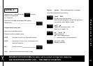
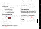
26
1 2 3 4 5 6 7 8
LN
5Vdc
15mA
+
–
+
–
9 10 11 12 13 14 15 16
Supply
1 ohm
4–20 mA
from transducer
Outputs
Linear Input Calibration (continued)
INPT
NONE
SP1.D
HI.SC
HI.SC
SPAN
SPAN
UNIT