


Electrical Installation
30
ELECTRICAL INSTALLATION
(continued)
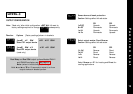
EN61010 - /CSA 22.2 No 1010.1 92
Compliance shall not be impaired when fitted to the final
installation.
Designed to offer a minimum of Basic Insulation only.
The body responsible for the installation is to ensure that
supplementary insulation suitable for Installation Category II or III is
achieved when fully installed.
To avoid possible hazards, accessible conductive parts of the final
installation should be protectively earthed in accordance with
EN6010 for Class 1 Equipment.
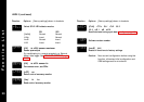
Output wiring should be within a Protectively Earthed cabinet.
Sensor sheaths should be bonded to protective earth or not be
accessible.
Live parts should not be accessible without the use of a tool.
When fitted to the final installation, an IEC/CSA APPROVED
disconnecting device should be used to disconnect both LINE and
NEUTRAL conductors simultaneously.
A clear instruction shall be provided not to position the equipment
so that it is difficult to operate the disconnecting device.
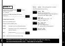
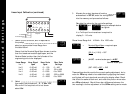
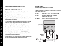
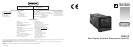
MODEL CN9412
TYPICAL CONNECTION DIAGRAM
The SSR driver output is allocated to SP1 and wired to switch the
load (heater) using an SSR
F1 Fuse: time lag type to IEC127. CSA/UL rating 250Vac
F2 Fuse: High Rupture Capacity (HRC) Suitable for
maximum rated load current
S1 Switch: IEC/CSA/UL Approved disconnecting Device
Comms option
(when fitted)
1 2 3 4 5 6 7 8
LN
5Vdc
15mA
+
–
+
–
12 13 14 15 16
Sensor
Output
SP1
SP2
Output
SSR
+
–
S1
Sensor
Supply
Line
Open in
alarm
state
9 10 11
Load
F2
F1
Neutral