


Advanced Settings
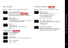
2.5 Therefore adjust
SPAn
to (-) 18 to correct error.
Notes: (1) After making the adjustment the reading will
immediately change. Allow time for the temperature
to stabilise at T
2
before making any further adjustment.
At this point, a
ZEro
adjustment may be needed, refer
to step 1 above.
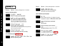
(2) Check that the temperature correctly stabilises at T
2
and then adjust setpoints to T
1
. If an error is present
at T
1
repeat from step 2.
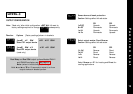
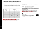
LINEAR INPUT CALIBRATION
In addition to the ten temperature inputs, the controller has five
linear input ranges which can be calibrated to display a range of
engineering units. This procedure involves making adjustments to
the controller’s
hi.SC
,
ZEro
and
SPAn
adjustments found in
function menu levels 2 and 3.
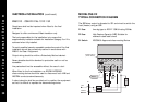
Note: The controllers linear inputs are in mV. If your transducer
provides an output in mA this should be converted to mV
by feeding the controller input via a high stability one ohm
resistor, see figure page 26. Other low Vdc signals can be
connected via a suitable voltage divider network to match
the controller input requirements.
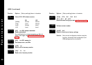
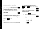
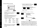
Calibration to Another Instrument (continued)
To make a correction when there are different errors across the scale.
2 Adjust using the function
2.1 Chose a temperature near the bottom and
another near the top of the scale.
2.2 Run the process at the lower temperature (T
1
).
Note the error (E
1
) between the controller and the
instrument readings.
2.3 Repeat at the upper temperature (T
2
) and note
error (E
2
).
2.4 Substitute the values for T
1
, T
2
, E
1
and E
2
in the
expression below to calculate
E
2
-E
1
X
hi.SC
=
SPAn
T
2
-T
1
For
hi.SC
settings see level 2.
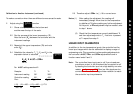
Example: T
1
T
2
Instrument reading 58° 385°
Controller reading 60° 400°
Error E
1
(-) 2° E
2
(-) 15°
(-15) - (-2) x 450 = (-13) x 450 = (-)17.9
385 - 58 327
25
SPAN
SPAN