


NI RF Signal Generators Getting Started Guide 32 ni.com
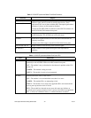
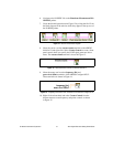
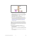
Figure 15. Frequency and Power Level Controls on the Block Diagram
11. Display the VI front panel by clicking it or by selecting Window»
Show Front Panel. Controls are displayed in which you can specify
a frequency and power level.
12. In the VI front panel power level (dBm) control, enter
0. In the
frequency (Hz) control, enter
100M (100 MHz).
13. In the VI front panel resource name control, enter the NI 5610
upconverter device name or the NI 5650/5651/5652 device name that
you specified in MAX (the NI 5610 upconverter module must be
associated with an AWG module. Refer to the Configuring the
NI 5670/5671/5672 in MAX section for more information about
associating a module.)
You can control continuous waveform generation using a Stop button.
A Stop button is typically used within a While Loop. This example places
a While Loop around the niRFSG Check Generation Status VI so that
signal generation continues and waveform status is continuously checked
until you click STOP.
Build a STOP button by completing steps 14 through 18.
14. Display the block diagram by clicking it or selecting Window»
Show Block Diagram.
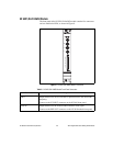
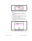
15. Select the While Loop on the Functions»Programming»Structures
palette.
16. Enclose the niRFSG Check Generation Status VI in the While Loop,
as shown in Figure 16.