


NI RF Signal Generators Getting Started Guide 30 ni.com
Appendix B: Building a Basic NI-RFSG Application
NI-RFSG includes several example applications for both LabVIEW and
LabWindows/CVI. These examples are intended to serve as interactive
tools, programming models, and as building blocks in your own
applications.
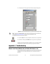
LabVIEW and LabWindows/CVI users can access all installed NI-RFSG
examples at Start»All Programs»National Instruments»
NI-RFSG»Examples. LabVIEW users can access NI-RFSG examples by
running LabVIEW and selecting Help»Find Examples to launch the
LabVIEW Example Finder.
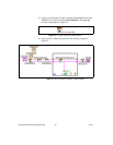
You can complete the following steps in LabVIEW to build a basic
NI-RFSG application for generating continuous sine wave signals:
1. Select Start»All Programs»National Instruments»<LabVIEW>»
LabVIEW to launch LabVIEW. The LabVIEW screen appears.
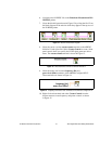
2. Click New, choose Blank VI, and click OK to create a blank VI.
3. Display the block diagram by clicking it or by selecting Window»
Show Block Diagram.
4. Activate the LabVIEW context help by pressing <Ctrl-H>.
5. Click the LabVIEW block diagram to launch the Functions palette.
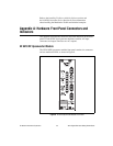
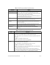
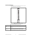
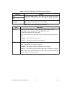
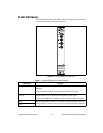
Table 10. NI 5650/5651/5652 RF Signal Generator Module Front Panel LEDs
LED Indications
ACCESS Indicates the basic hardware status of the NI 5650/5651/5652 module.
OFF—The module is not yet functional or has detected a problem with a PXI
power rail.
AMBER—The module is being accessed.
GREEN—The module is ready to be programmed.
ACTIVE Indicates the status of the NI 5650/5651/5652.
OFF—The module is in an uninitialized state; there is no error.
AMBER—The module PLLs are attempting to lock.
GREEN—The module is generating a signal; applicable PLLs are locked.
RED—The module has detected an error state; this may indicate lock failure in
an applicable PLL, a self-test or calibration failure, or a thermal shutdown
condition.