


NI RF Signal Generators Getting Started Guide 24 ni.com
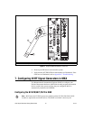
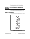
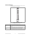
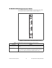
Table 3. NI 5610 RF Upconverter Module Front Panel Connectors
Connector Purpose
TO AWG CLK IN Output terminals for replications of the upconverter 10 MHz frequency
reference signal, which is useful for driving other devices. Each
replication is 180° out-of-phase with the other. The output signal at these
connectors is always on and cannot be disabled.
Connect the TO AWG CLK IN connector to the CLK IN connector on
the NI 5421/5441/5442 module front panel.
10 MHz OUT
REF IN Routes an external frequency reference signal that can be propagated to
the PXI backplane. The NI 5610 can lock to this signal.
IF INPUT Routes the IF signal from the NI 5421/5441/5442 AWG module for
frequency translation.
Connect to the CH 0 output on the NI 5421/5441/5442 front panel.
LOCAL OSC OUT 0 Output terminal for the auxiliary local oscillator signal.
RF OUTPUT Output terminal for the upconverted signal at the requested RF
frequency.
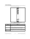
Table 4. NI 5610 RF Upconverter Module Front Panel LEDs
LED Indications
ACCESS Indicates the basic hardware status of the NI 5610 module. This LED functions
identically to the ACCESS LED on the AWG module front panel.
OFF—The module is not yet functional or has detected a problem with a PXI
power rail.
AMBER—The module is being accessed.
GREEN—The module is ready to be programmed.
ACTIVE Indicates the status of the NI 5610 PLLs.
OFF—The module is in an uninitialized state; there is no error.
AMBER—The module PLLs are attempting to lock.
GREEN—The module is in a ready state; applicable PLLs are locked and the
reverse power protection circuit is closed.
RED—The module has detected an error state; this state may indicate an
overload (reverse power protection circuit is open), lock failure in an applicable
PLL, a self-test or calibration failure, or a thermal shutdown condition.