


© National Instruments Corporation 25 NI RF Signal Generators Getting Started Guide
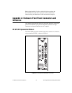
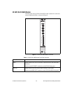
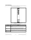
NI 5421/5441 AWG Module
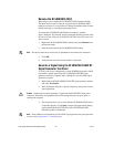
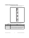
The front panel of the NI 5421/5441AWG module contains five connectors
and two multicolor LEDs, as shown in Figure 9.
Figure 9. NI 5421/5441 AWG Module Front Panel
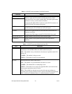
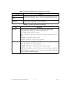
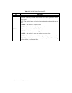
Table 5. NI 5421/5441 AWG Module Front Panel Connectors
Connector Purpose
CH 0 Output terminal for an IF waveform for upconversion to the desired RF
frequency.
Connect to the IF INPUT connector on the NI 5610 front panel.
CLK IN Output terminal for the AWG module reference clock signal.
Connect to the REF OUT connector on the NI 5610 module front panel.
PFI 0
PFI 1
NI PXI-54XX
ACCESS ACTIVE
CLK
IN
CH 0
DIGITAL DATA & CONTROL