


1
31AE5MLG729
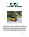
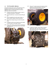
YARD MACHINES SNOW THROWER
Model 31AE5MLG729
• Serial Number 1G024B10168
• Two Stage – 4 Cycle HMSK80-110 – 10.5 HP
• 28” Xtreme Auger
• 21” Intake Height
• Tecumseh Engine With Electric Start
• Power Steering
• 4 – Way Discharge Chute Control
• 6 Forward Speeds and 2 Reverse Speeds
• Built in Halogen Light
• Fully assembled with oil in engine
• The 4-way discharge chute control: for quick and
easy snow directional changes.
• Power Steering: For ultimate maneuverability
• XTREME Auger: Break down of ice and snow
before pushing the pieces into the impeller.
• Built-in Halogen Light: For use in early morning
or evening.
GENERAL INFORMATION
The Owner’s Manual packet includes and engine man-
ual, extra shear pins and cotter pins as well as a packet
containing a sample of Sta-Bill fuel stabilizer that will
treat up to 2 ½ gallons of regular gas.
CAUTION: When assembling the handle for the
first time, use caution when lifting the handle.
The shift lever rod can get caught on the lower
handle cross member and if forced into position
can bend the spring shift lever. If necessary,
move the shift rod in front of the cross member
as you raise the handle into position.
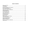
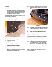
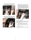
There are two Supplement Sheets dated July 19 2004
and July 20, 2004 – Subject: Connector Sleeve on Two
Stage Snow Thrower shift rod. (Styles: E, F, H, K, L, N,
O, P and Q.)
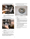
Vibration may cause the rod connector sleeve to slide
up out of position. The remedy is to slide the connecter
sleeve fully down. Secure it in place by placing a rub-
ber bushing over the top of the lower shift rod OR the
upper shift rod.. (A small piece of gas line can be used
as a bushing.) This will prevent the sleeve from sliding
up the shaft. See Figure 1.
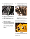
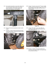
Rubber bands hold the Auger and Drive control cables
in their respective nylon pulleys during shipping and
generally break during assembly of the handle.
Remove any pieces of rubber band after assembly.
Figure 1
Rod Connector Sleeve
Rubber Bushing
31AE5MLG729 Snow Thrower