


14
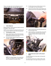
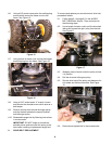
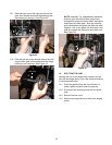
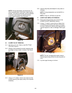
NOTE: During reassembly note that there are
two mounting holes in the friciton wheel support
bracket. The friciton wheel disc must be installed
in the left hand hole as you face the friction
wheel support bracket. See Figure 44.
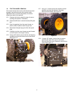
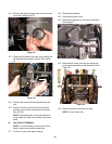
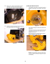
16. AUGER PULLEY REMOVAL
16.1. Split the unit in two. Refer to the SPLITTING
THE UNIT Section.
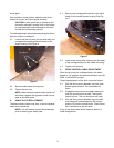
16.2. Wedge a 2x4 between the spiral assembly and
the auger hosing to hold it in place. See Figure
45.
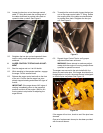
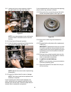
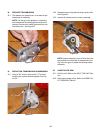
16.3. Using a 1/’2” socket, remove the screw and flat
washer securing the auger pulley to the impeller
assembly.
16.4. Inspect the pulley and adapter for any wear or
damage.
NOTE: During reassembly use Loctite 242 on
the screw.
NOTE: Torque to 160-200 inch pounds.
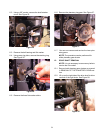
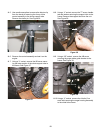
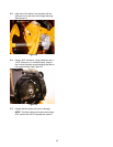
17. AUGER AND IMPELLER REMOVAL
17.1. Remove the Auger Pulley as covered in the
AUGER PULLEY REMOVAL Section..
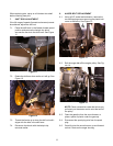
17.2. Using a ½” socket, remove the two flange lock
nuts securing the bearing housing to the auger
housing. Remove the bearing housing and bear-
ing and inspect for wear or damage. See Figure
46.
NOTE: The two carriage bolts used to secure
the bearing housing are held in place by push-on
nuts.
17.3. Lay the auger housing on its face.
Figure 44
Assemble in left mounting hole
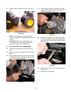
Figure 45
2x4
Auger Pulley Flat Washer Screw
Figure 46
Flange Lock Nuts