


15
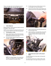
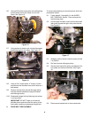
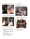
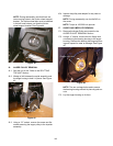
17.4. Using a 1/2 “ socket, remove the four (two on
each side) hex screws securing the auger
assembly to the auger housing. See Figure 47.
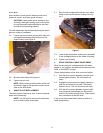
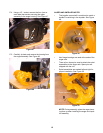
17.5. Carefully tip back and remove the housing from
the auger assembly. See Figure 48.
Figure 47
Hex Screws
Figure 48
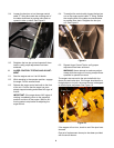
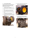
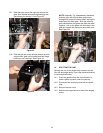
AUGER AND IMPELLER NOTES
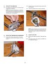
• The impeller worm shaft is machined to match a
double D machining in the impeller. See Figure
49.
• Hex flange bearings are used at the ends of the
auger axle.
• There a four shear pins used to attach the spiral
assemblies to the auger axle. Spare pins are
shipped with the unit.
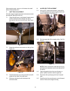
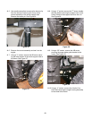
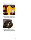
• Spiral assemblies are marked left and right for
proper installation. See Figure 50.
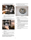
NOTE: During assembly, place the auger hous-
ing face up when installing the auger and impel-
ler assembly.
Figure 49
Double “D” Machining
Figure 50
Spiral Assembly