


12
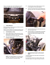
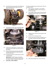
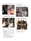
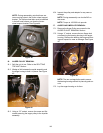
14.5. Use needle nose pliers to remove the hairpin clip
from the clevis pin securing the 4-way chute
control assembly to the chute support tube.
Remove the clevis pin. See Figure 36.
14.6. Remove the control assembly and set it on the
engine.
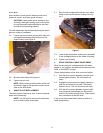
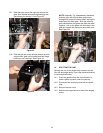
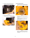
14.7. Using a ½” socket, remove the AB screw secur-
ing the lower portion of the chute support tube to
the frame. See Figure 37.
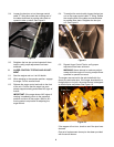
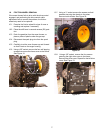
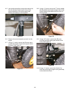
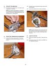
14.8. Using a ½” socket, remove the TT screw, handle
tab and washer securing the support tube to the
frame. Remove the support tube from the unit.
See Figure 38.
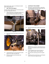
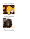
14.9. Using a 3/8” socket, remove the AB screw
securing the auger cable guide bracket to the
frame. See Figure 39.
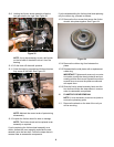
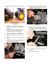
14.10.Using a ½” socket, remove the 4 bolts (2 on
each side) securing the auger housing assembly
to the wheel drive frame.
Figure 36
4-Way Chute Control
Hairpin Clip
Figure 37
AB screws
Figure 38
Support Tube
Frame Screws
Figure 39
Auger Cable Bracket