


8
j Horizontal (R.A.) Loc
k
:
Controls the manual horizontal rotation of the telescope.
Loosen the horizontal lock counterclockwise to unlock the telescope, enabling it to
be freely rotated by hand about the horizontal axis. Tightening the horizontal lock
clockwise prevents the telescope from being rotated manually, but engages the hor-
iz
ontal motor drive clutch for AutoStar operation. When polar aligned, the horizon-
tal lock serves as the Right Ascension or R.A. lock.
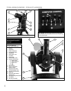
1) Computer Control Panel (see Fig. 2)
A. ON/OFF Switch
: Turns the Computer Control Panel and AutoStar
handbox ON or OFF.
Note: Always remove the batteries if they are not to be used for a long
period of time.
B. Auxiliary (AUX) Ports (2): Provide connection for current and future
Meade accessories. See
OPTIONAL ACCESSORIES
, page 42.
C. Handbox (HBX) Port: Plug the AutoStar handbox into this port.
D. 12v: The 12v connector is designed to accept an external power
supply such as the optional #541 AC Adapter or the #607 Power Cord
(see
OPTIONAL ACCESSORIES, page 42). When one of the external
power supply options is used, the internal batteries are disconnected
from the power circuit.
E. LED: The red power indicator light illuminates when power is supplied
to the connected handbox and to the telescope’s motor drive.
1! Base Housing: Supports the telescope for placement on a flat, level surface,
such as a tabletop or tripod.
1@ Battery Compartment (not shown, underneath base): Install eight
user-supplied AA batteries in this compartment. See page 12 for more
information.
1# Right Ascension (R.A.) Setting Circle: See page 53 for detailed information.
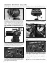
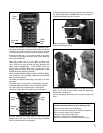
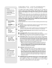
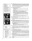
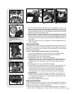
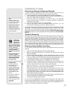
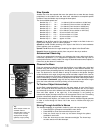
1$ Flip-Mirror and Flip-Mirror Control Knobs: ETX telescopes include an internal
mirror. With the flip-mirror control in the “up” position, as shown in
Fig. 3a, light is
diverted to the eyepiece. With the flip-mirror control in the “down” position, as
shown in
Fig. 3b, light proceeds straight out the photo port for photography. See
PHOTOGRAPHY, page 39.
Note: The flip-mirror control is in the “up” position when the control is
vertical (perpendicular to the telescope tube).To place the flip-mirror in the
“do
wn”
position, turn the control until it is horizontal.
1% Photo P
or
t
:
Attach an
y 35mm camer
a with a removable lens to this port using an
optional #64ST T-Adapter or attach the #932 Erecting Prism for correctly
oriented images through the eyepiece. See
OPTIONAL ACCESSORIES, page 42.
1^ Declination (Dec.) Setting Circle (on left fork arm): See page 53 for detailed
information.
1& SmartFinder Alignment Screws: Adjust these screws to align the SmartFinder.
See pages 13 and 14 for more information.
1* LNT (Level North Technology) Module: This assembly has sensors which auto-
matically points the telescope North, and detects the level and tilt of the telescope
dur
ing automatic alignment.
See page 17 f
or more inf
or
mation about Automatic
Alignment. The LNT bracket also contains a LNT Module which supplies the time
and date to AutoStar. The time is set at the factory. See
ATOMIC TIME UPDATE
MODULE PORT
below.
1( ATOMIC TIME UPDATE MODULE Port: Attach Meade’s ATOMIC TIME UPDATE
MODULE
optional accessor
y into this por
t.
Y
our telescope’
s time is set at the f
ac
-
tor
y bef
ore it is shipped, b
ut the
A
T
OMIC
TIME UPDATE MODULE
allo
ws y
our tele
-
scope to update the time module from the NIST atomic cloc
k in Fort Collins,
Colorado.
2) Dust Cap: Unthread the dust cap counterclockwise from the front lens of the
telescope.
1* W
ant to lear
n more about
aligning the
SmartFinder
?
See pages 13.
Definitions
Throughout this manual,
you will notice the terms
"Alt/Az," "Right
Ascension," and
"
Declination." Alt/Az or
more properly, altazimuth,
is frequently used to refer to
altitude or Declination (the
up-and-down vertical
movement of the telescope)
and
azimuth or Right
Ascension (the side-to-side
horizontal movement of the
telescope). Right Ascension
is abbreviated as "
R.A."
and Declination as "Dec."
Fig. 3a: Flip mirror control in
the “up” position.
Fig. 3b: Flip mirror control in
the “down” position.
1( Note: The dust cap
should be replaced
after each obser
ving
session and the
power turned off to
the telescope
.
V
erify
that any dew that
might have collected
during the observing
session has
evaporated prior to
replacing the dust
cap
. Do not
o
v
er
tighten.