


APPENDIX D:CHANGING THE
LNT MODULE BATTERY
56
The LNT Module uses a lithium coin CR2023 batter
y that will last about 5 years and
is installed with the original LNT Module assembly. After you replace the battery, you
will need to recalibr
ate the telescope’s sensors and reset the time and date.You will
need a new battery. Also, you may use Meade’s optional Atomic Time Update
Module, although this is not necessary.
T
o replace the battery:
1.
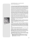
Remove the top alignment screw cap/long bolt from the LNT Module. See
Fig.
54
.
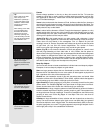
2. Remove the side alignment screw cap/long bolt from the LNT Module. Take note
that there are two springs inside the LNT. One spring sits between the top and
bottom of the unit. The second spring is on the side of the unit that rests
between the bottom and the top sections. One long bolt passes through the top
spring and the other long bolt passes through the side spring. Set the springs
aside as you will need to replace it later in this assembly . See
Fig. 55 and 56.
Important Note: Note there is some wiring inside the LNT Module. Be careful
not to pull on the wiring. If it is necessary to move the wiring aside, do so
carefully.
3. Carefully lift the top section of the unit from the bottom section. Do not remove
the bottom section or disassemble the rest of the unit.
4. Remove the old battery. Note the spring.
5. Insert the new (user-supplied) battery. Take care to orient the battery so that the
side with the battery markings is facing the top.
6. Replace the top spring in place and the LNT Module cover.
7. Replace the top bolt and tighten the cap to a firm feel.
8. Hold the side spring in place with your fingers and slide the spring between
between the top and bottom sections. The spring should line up with the
mounting holes for the side long bolt. Slide the long bolt through the side hole,
then through the spring and finally through the bottom of the LNT Module and
tighten to a firm feel.
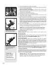
9. Next you will need to recalibrate the LNT Module sensors. Select Calibrate
Sensors from the Setup: Telescope menu. A scrolling message displays.
10. The message prompts you to place the telescope in the home position:
• Loosen the telescope’s vertical lock (
6, Fig. 1B). This will allow you to move
the telescope’
s optical tube up and do
wn.
•
Le
v
el the tripod head. See
Step #3g, page 12.
Le
v
el the optical tube by
lining up 0
° on the Dec setting circle (
16,
Fig. 1a
) with the Dec pointer
(the small molded triangle under the setting circle).
•
Retighten the vertical lock (
6,
Fig. 1b
) to a fir
m feel only.
•
Unloc
k the hor
iz
ontal loc
k (
9,
Fig.
1a
). This will allo
w y
ou to rotate the
telescope tube and f
or
k arm assembly.
•
Gr
asp the telescope b
y a f
or
k ar
m and rotate the telescope
countercloc
kwise
until it stops.
•
Re-loc
k the Hor
iz
ontal loc
k (
9,
Fig.
1
).
11. Press ENTER.The telescope will automatically find North, detect level and the tilt
of you telescope, and calibrate the sensors.
12. Next, follow the instructions included with the Atomic Time Update Module
optional accessory to reset the clock.
OR
Enter the date and time man
ually using the Date and
Time options in the Setup
men
u.
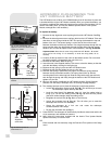
Top Alignment
screw hole
Spring
Spring
Batter
y
Side
Alignment
screw hole
Side
Alignment
screw
Side
Alignment
screw hole
Cover
Top Alignment
screw
Top
Alignment
screw
Atomic Time
Update Port
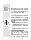
Fig. 54: The LNT Module, with
alignment scre
ws and Atomic Time
Update port visible.
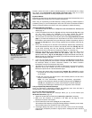
Fig. 55: Interior side view of LNT
Module.
Fig. 56 Interior top view of
SmartFinder unit.