23
Section 3 Adjustments
03/11/03
Z52®, Z60® & Z72® Zero Turning Radius Mowers Accu-Z 356-005M
Land Pride
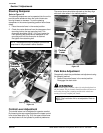
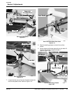
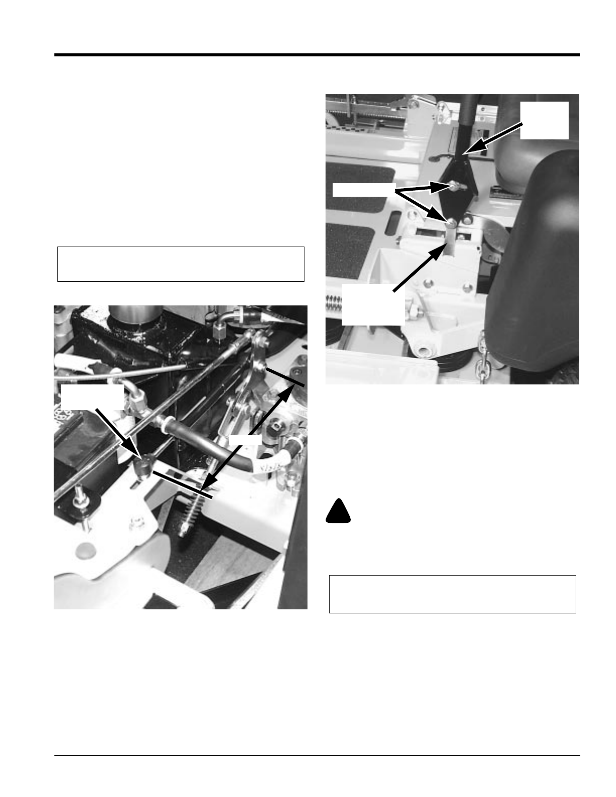
Steering Dampener
Refer to Figure 3-5:
The steering dampeners are incorporated into the unit to
provide some resistance when the control levers are
moving forward or rearward. To set the steering
dampeners in the correct operating position follow these
steps:
1. Place the control lever in the neutral position.
2. Check the center distance from the dampeners front
mounting hole to the rear mounting hole. This
dimension should be 8 9/16”. If it is not, loosen the
front attaching bolt and slide the dampener in the
mounting slot until this dimension is attained.
Re-tighten front attaching bolt.
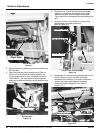
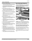
Control Lever Adjustment
The control levers can be adjusted for operator comfort.
By loosening the cap screws that attach the upper control
lever to the lower lever (Fig. 5-6), the upper control lever
can be pivoted to fit the operator s personal preference.
The control levers should be adjusted so that they align
with each other when in the neutral position.
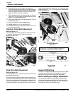
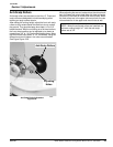
Park Brake Adjustment
Occasionally checkthe park brakes and adjustment using
the following method:
1. Position the control levers in the neutral position.
Disengage the deck clutch.
!
WARNING!
Make certain mower is secure when it is raised and placed on
the jack stands. The jack stands should not allow the mower to
move when the engine is running and the drive wheels are
rotating. Use only certified jack stands.
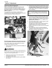
NOTE: The dampener must not bottom out when the
pump lever is fully stroked in either direction.
19081
Steering Dampener Adjustment
Figure 3-5
Steering
Dampener
8.54”
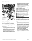
Control Lever Adjustment
Figure 3-6
19082
Cap Screw
Lower
Control
Lever
Upper
Control
Lever
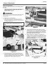
NOTE: The front brake link is not adjustable. Refer to
Figure 3-7.


