


22
Section 3 Adjustments
Z52®, Z60® & Z72® Zero Turning Radius Mowers Accu-Z 356-005M 03/11/03
Land Pride
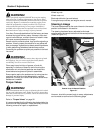
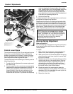
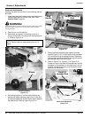
Control Lever Stops
The control lever stops (Figure 3-3)are designed to do two
things: First, and most important, they must keep the
pumps from bottoming out internally. Second, the stops
may be adjusted to help drive straight when the control
levers are pushed forward against the stops.
To keep the pumps from bottoming out internally use the
following procedure:
1. To make the first adjustment the mower engine must
NOT be running.
2. Check to make sure the control levers are against the
stops before the pumps are bottomed out internally. To
do this, gently and slowly move the control levers
forward and feel if there is some resistance on the
pump lever before the control levers hit the stops.
Check one side at a time. If you sense that the pump
arms are stopping the forward motion of the control
arms, loosen the jam nut on the adjustable stop of the
corresponding side and turn the stop (set screw)
inward to stop the control levers slightly before the
pump bottoms out.Lock in placewhen theadjustment
is correct by re-tightening the jam nut.
3. Do this for each side.
To adjust the stops for driving straight when control levers
are against the stops during operation:
Determine which drive tire is rotating too fast when both
control levers are against the stops. Then stop the mower
and loosen the lock nut on the side which is rotating too
fast and turnthe stop (setscrew) inward tostop the control
lever sooner. Tighten the lock nut on the stop and test
again. Repeat this procedure until unit drives straight.
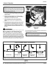
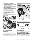
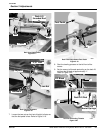
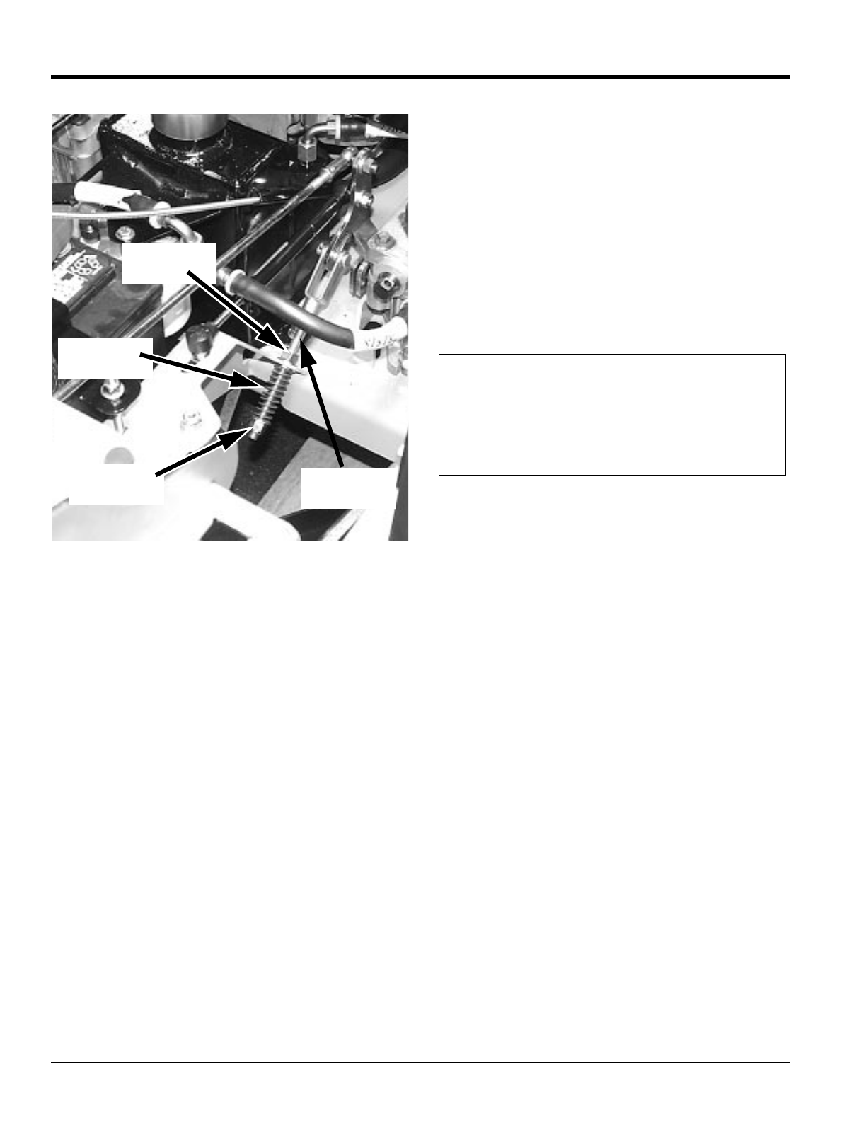
Reverse Spring Adjustment
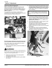
Refer to Figure 3-4:
The reverse spring is designed to bring the control levers
to the neutral position after they are released from the
reverse position.
To adjust:
1. Make certain the control lever neutral adjustment is
correct. If not, refer to Steering Linkage section.
2. When control lever is in the reverse position thespring
should force the control lever to return to neutral after
the lever is released.
3. Adjustthe topnylock nut on the springlinkage untilthe
control lever returns to the neutral position from the
reverse position properly. Tightening the nylock nut
will cause the control lever to travel forward less
before stopping. Loosening the nylock nut will allow
the control lever to travel farther forward.
4. Check the length of the reverse spring when the
control lever is in the neutral position. This dimension
should be 1 7/8”. If it is not, adjust the lower nylock nut
until the dimension is achieved.
5. Repeat for other side.
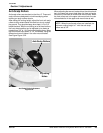
19081
Reverse Spring
Figure 3-4
Top Nylock
Nut
Reverse
Spring
Lower
Nylock Nut
Spring
Linkage
NOTE: Since this is a hydrostatic drive, variables
such as temperature of oil, efficiency of pumps and
motors, tire pressure etc., may effect the consistency
of the ability to rely on the stops to drive straight
without the operator making minor steering
adjustments with the control arms.