


13
Section 2: Optional Assembly & Set-up
10/08/14
SB1051, SB1064, SB1574, & SB2584 with S/N 881640- Snow Blowers 370-027M
Table of Contents
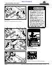
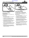
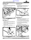
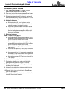
Wear Bar, Lower
Refer to Figure 2-8:
1. Attach wear bar (#1) to bottom of Snow Blower frame
with 3/8"-16 x 1" GR5 plow bolt (#2) and hex flange
lock nut (#3).
2. Tighten lock nut to the correct torque.
Lower Wear Bar Assembly
Figure 2-8
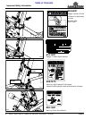
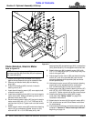
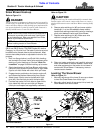
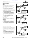
Skid Shoes, Outer
Refer to Figure 2-9:
1. Attach right-hand skid shoe (#1) to upper hole “A”
with 3/8"-16 x 1" GR5 carriage bolt (#2A) and hex
flange lock nut (#3).
2. Attach right-hand skid shoe (#1) to hole “B” or “C”
with 3/8"-16 x 1" GR5 carriage bolt (#2B) and hex
flange lock nut (#3).
3. Tighten lock nuts to the correct torque.
4. Repeat steps 1 and 3 above for the left-hand skid
shoe.
Outer Skid Shoe Assembly
Figure 2-9
33240
33241
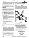
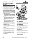
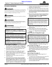
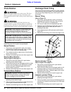
Wear Bars, Outer
Refer to Figure 2-10:
1. Attach adjustable wear bars (#1) to either the upper
or to the lower holes in the side panels with
3/8"-16 x 1 1/4" GR5 carriage bolt (#2) and hex
flange lock nut (#3).
2. Tighten lock nuts to the correct torque.
Outer Wear Bar Assembly
Figure 2-10
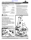
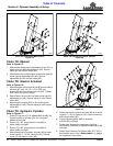
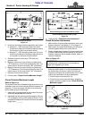
Skid Shoes, Inner
Refer to Figure 2-11:
1. Attach skid shoe mounts (#3) to both sides of Snow
Blower frame with backing plates (#4),
3/8"-16 x 1" GR5 cap screws (#5), and hex flange
lock nuts (#6). Tighten lock nuts to the correct torque.
2. Insert skid shoes (#1) into skid shoe mounts (#3).
3. Install 1" spacer (#10), 1/2" spacer (#9), and four flat
washers (#7) over shaft of each skid shoe.
4. Secure skid shoes (#1) with 1/4" x 1 3/4" wire
retaining pins (#8).
5. Make certain wire retainers are caught over end of
pins to keep skid shoes from falling out.
Inner Skid Shoe Assembly
Figure 2-11
33242
33239