


11
Section 2: Optional Assembly & Set-up
10/08/14
SB1051, SB1064, SB1574, & SB2584 with S/N 881640- Snow Blowers 370-027M
Table of Contents
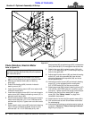
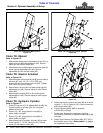
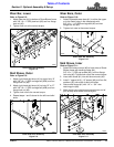
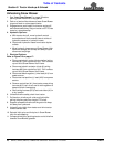
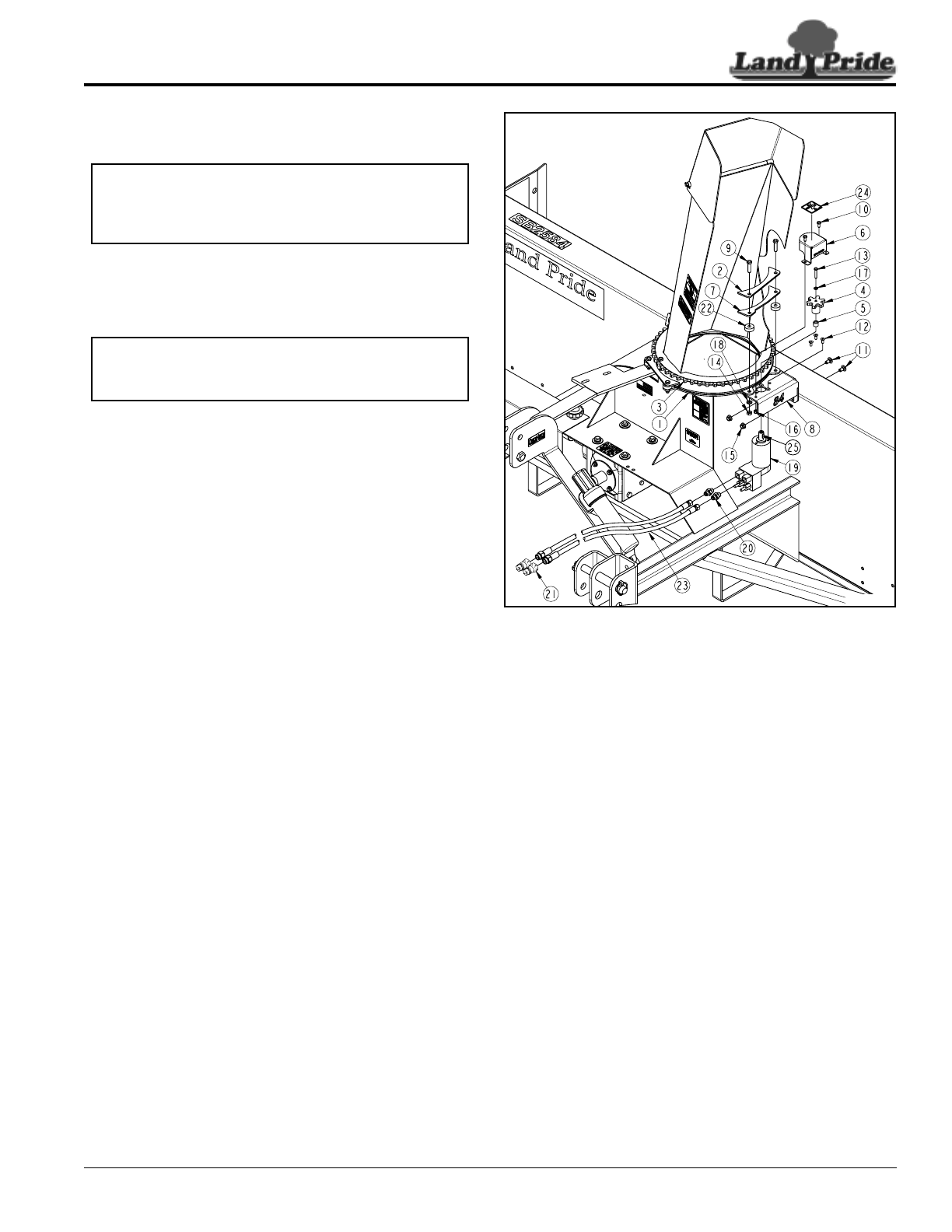
Chute Rotation, Hydraulic Motor
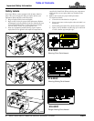
Refer to Figure 2-4:
1. Rotate discharge chute clockwise until chute is
against chute stop and can not be rotated further.
2. Remove bolts (#9), bearing strap (#2), chute
bearings (#22), lock washers (#18), and nuts (#14).
3. Attach hydraulic mounting plate (#8) as follows:
SB1051 & SB1064 Models
Attach mounting plate(#8) stamped 51/64 to blower
chute ring (#1) with bolts (#9), existing strap (#2),
chute bearings (#22), lock washers (#18), and hex
nuts (#14). Do not tighten nuts at this time.
SB1574 Model
Attach mounting plate (#8) stamped 74 to blower
chute ring (#1) with bolts (#9), new strap (#7), chute
bearings (#22), lock washers (#18), and hex
nuts (#14). Do not tighten nuts at this time.
SB2584 Model
Attach mounting plate stamped 84 (#8) to blower
chute ring (#1) with bolts (#9), new strap (#7), chute
bearings (#22), lock washers (#18), and hex
nuts (#14). Do not tighten nuts at this time.
4. Continue to attach hydraulic mounting plate (#8) to
the Snow Blower with 3/8"-16 x 3/4" GR5 carriage
bolts (#11) and hex flange lock nuts (#15). Do not
tighten lock nut at this time.
5. Attach hydraulic motor (#19) to hydraulic mounting
plate (#8) with hex socket countersunk bolts (#12).
Tighten countersunk bolts.
6. Install gear spacer (#5) over output shaft of hydraulic
motor (#19).
7. Attach drivegear (#4) and key(#25) to output shaft of
hydraulic motor (#19) with M6 x1x35GR8.8
bolt (#13) and spring lock washer (#17). Tighten
M6 bolt to the correct torque.
8. Adjust hydraulic mounting plate (#8) until drive
sprocket (#4) has minimal clearance between drive
sprocket (#4) and chute driven sprocket (#3).
9. Hold hydraulic mounting plate (#8) in its adjusted
position and tighten 3/8"-16 GR5 bolts (#9 & #11) to
the correct torque.
IMPORTANT: Adjustmentscrews onhydraulicmotor
are preset at the factory. Do not change factory
settings. Changing factory settings can cause
structural damage to the Snow Blower.
NOTE: Existing bearing strap (#2) is reused with
SB10 Series Snow Blowers. The SB15 and SB25
Series Snow Blowers uses new bearing strap (#7).
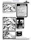
Chute Rotation Powered By Hydraulic Motor
Figure 2-4
10. Install gear cover (#6) as follows:
SB1051 & SB1064 Models
Attach gear cover (#6) stamped 370-534D to
hydraulic mounting plate (#8) with 1/4"-20 x 5/8"
GR5 bolts (#10) and hex nylock nuts (#16). Tighten
nylock nuts to the correct torque.
SB1574 & SB2584 Models
Attach gear cover (#6) stamped 370-613D to
hydraulic mounting plate (#8) with 1/4"-20 x 5/8"
GR5 bolts (#10) and hex nylock nuts (#16). Tighten
nylock nuts to the correct torque.
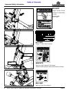
11. Screw 9/16" MORB x 9/16" MJIC adapters (#20) to
ports in hydraulic motor (#19) until tight.
12. Screw 3/8" x 60" long hydraulic hoses (#23) to
adapters (#20) until tight.
13. Screw quick disconnect couplings (#21) (couplings
furnished by customer) to other end of hydraulic
hoses (#23) until tight.
14. Attach High Pressure Fluid Decal 848-747C (#24) in
the location shown. See “Safety Labels” on page 4
for installation instructions.
15. Coil Hydraulic hoses (#23) around Snow Blower
mainframe for safe keeping.
35477