


8
Section 1: Standard Assembly & Set-up
SB1051, SB1064, SB1574, & SB2584 with S/N 881640- Snow Blowers 370-027M
10/08/14
Table of Contents
Section 1: Standard Assembly & Set-up
Tractor Requirements
Tractor horsepower and hitch category should be within
the range noted below. Tractors outside the horsepower
range must not be used.
Tractor Horsepower Rating
SB10 Series . . . . . . . . . . . . . . . . . . . . .18 to 32 HP
SB15 Series . . . . . . . . . . . . . . . . . . . . . . 30-59 HP
SB25 Series . . . . . . . . . . . . . . . . . . . . . 43-105 HP
Hitch Type:
SB10 Series . . . . . . . . . . . . . . . . . . . .3-Point Cat. I
SB15 Series . . . . . . . . . . . . . . . . . . . .3-Point Cat. I
SB25 Series . . . . . . . . . . . . . . . . .3-Point Cat. I & ll
PTO Speed. . . . . . . . . . . . . . . . . . . . . . . . . .540 RPM
Hydraulic Quick Disconnect Outlets (Optional)
Chute Rotational Adjustment. . . . . . . Duplex Outlet
Chute Tilt Adjustment . . . . . . . . . . . . Duplex Outlet
Tractor Weight . . . . . . . . . . . . . . See Warning Below
!
WARNING
Ballast weights may be required to maintain steering control.
Refer to your tractor’s operator’s manual to determine proper
ballast requirements.
Torque Requirements
Refer to “Torque Values Chart” on page 38 to
determine correct torque values for common bolts. See
“Additional Torque Values” at bottom of chart for
exceptions to standard torque values.
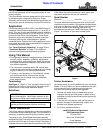
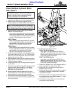
Dealer Set-up Instructions
When included, it is simpler to assemble the optional
outer skid shoes or outer wear bars before removing the
shipping crate. See “Skid Shoes,Outer” or “Wear Bars,
Outer” on page 13 for detailed installation instructions.
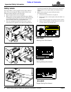
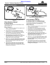
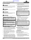
Loading & Unloading
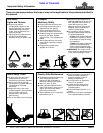
Refer to Figure 1-1:
There are two lifting holes (one on each end panel).
These lift holes are provided for attaching a lift chain to
the Snow Blower during loading and unloading.
Lift Points
Figure 1-1
33248
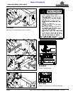
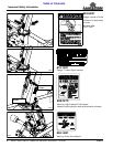
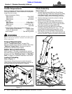
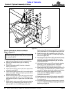
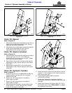
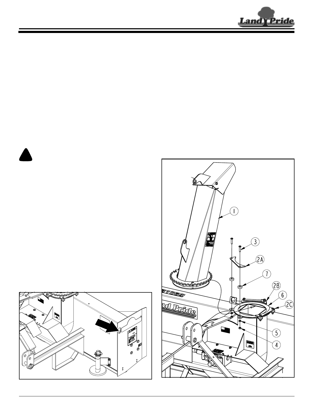
Chute Assembly
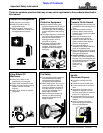
Refer to Figure 1-2:
1. Remove bearing strap (#2A) from Snow Blower
housing. Keep cap screws (#3), bearing strap (#2A),
chute bearings (#7), lock washers (#5), and hex
nuts (#4) for reattachment of discharge chute (#1).
2. Position discharge chute (#1) so that it is facing
straight back as shown.
3. Keep chute facing straight back. Slide base of
discharge chute (#1) over UHMW chute bearing
ring (#6) until base of chute is fully under the other
two remaining bearing straps (#2B & 2C).
4. Reattach bearing strap (#2A) to Snow Blower
housing by inserting existing 3/8"-16 x 1 1/2" cap
screws (#3) through bearing strap (#2A), chute
bearings (#7), and Snow Blower housing flange.
5. Secure bearing strap with existing lock washers (#5)
and hex nuts (#4). Tighten nuts to the correct torque.
Chute Assembly
Figure 1-2
33255