


14
Section 2: Adjustments
RCS3596, RCSM3596, RCS3510 & RCSM3510 Series Rotary Cutters 312-708M
6/26/06
Land Pride
Table of Contents
Leveling Procedure
There are three primary adjustments that should be
made prior to actual field operations:
a. Deck level from left to right
b. Tractor lower link height
c. Tailwheel height
Proper adjustment of each of these items will provide for
higher efficiency, improved cutting performance and
longer blade life. The following tools will be needed:
a. Pliable tape measure
b. Spirit or carpenter’s level
c. Open end or hex end wrench or socket set
d. Protective gloves
Having completed the “Tractor Hook-up”, locate the
tractor on a flat, level surface.
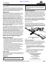
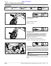
1. Use the tractor’s hydraulic 3-point control to lower the
cutter until the front of the skid shoes barely touch the
ground.
2. Place a spirit level or other suitable leveling device left
to right on the front of the cutter deck. Adjust either
one or both of the tractor’s lower link height
adjustments to level the deck from left to right. Some
tractors have only a single adjusting crank.
3. Similarly, place a level front to rear on either of the
main deck channels. Lower or raise tailwheel to level
the cutter deck from front to rear.
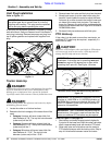
!
DANGER!
Engage parking brake, disengage PTO, shut off tractor and
remove key before proceeding. Ensure that all moving parts
have come to a complete stop before dismounting from the
tractor.
!
CAUTION!
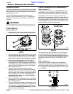
Wear a pair of gloves when performing this operation. Go to the
back of the cutter and carefully rotate one dishpan and attached
two blades to the position shown in Figure 2-1. Avoid direct
contact with the cutting edge of the blade.
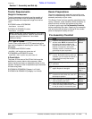
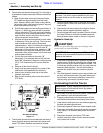
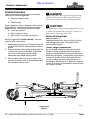
Minimum Cutting Height
Refer to Figure 2-1
Measure the distance from the end (cutting tip) of the
blade to the ground surface. This distance is the
minimum cutting height.
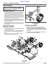
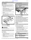
Cutter Height Adjustment
The unit is equipped with a ratchet jack or hydraulic
cylinder for cutting height adjustment. The hydraulic
selection includes stroke control spacers to set cutting
height. Stroke control spacers consist of cast steel
halves and a spring clip. To adjust height, simply extend
the hydraulic cylinder with the tractor hydraulics and
remove or replace the stroke control spacers for the
desired height. Each spacer is 1”. Retract the hydraulic
cylinder. Store stroke control spacers on hydraulic hose
near hydraulic cylinder.
Section 2: Adjustments
Cutting Height
Figure 2-1
20712
Cutting Height