


13
Section 1: Assembly and Set-Up
6/26/06
RCS3596, RCSM3596, RCS3510 & RCSM3510 Series Rotary Cutters 312-708M
Land Pride
Table of Contents
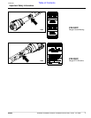
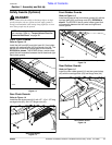
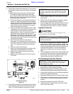
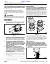
3. The driveline will require shortening if it is too long to
fit between the tractor and cutter. Shorten driveline as
follows:
a. Raise 3-point lower arms until cutter and tractor
PTO shafts are approximately level with each
other. Securely block cutter frame in this position.
Set tractor in park, shut tractor engine off, set park
brake and remove switch key.
b. Pull driveline apart into two sections as shown in
Figure 1-9. Attach the outer driveline universal
joint to the tractor PTO shaft and inner driveline
universal joint to the cutter gearbox shaft. Pull on
each driveline section to be sure the universal
joints are secured to the shafts.
c. Hold the driveline sections parallel to each other
to determine if they are too long. The inner and
outer shields on each section should end
approximately 1" short of reaching the universal
joint shield on the adjacent section (see “B”
dimension). If they are too long, measure 1" (“B”
dimension) back from the universal joint shield
and make a mark at this location on the inner and
outer driveline shields.
d. Cut off the inner shield at the mark (“X”
dimension). Cut the same amount off the inner
shaft (“X1” dimension). Repeat cut off procedure
(“Y”&“Y1” dimensions) to the outer driveline
half.
e. Remove all burrs and cuttings.
f. Apply multi-purpose grease to the inside of the
outer shaft and reassemble the driveline.
g. Attach inner driveline yoke end to the cutter
gearbox input shaft.
h. Attach outer driveline yoke end to the tractor's
PTO shaft.
Driveline Shortening
Figure 1-9
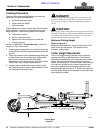
4. The driveline should now be moved back and forth to
insure that both ends are secured to the tractor and
cutter PTO shafts. Reattach any end that is loose.
22311
5. Hook driveline safety chain in the hole in the inner
driveline guard. Attach the other end to the cutter’s
main frame.
6. Start tractor and raise cutter just enough to remove
blocks used to support the deck in step 3a.
7. Slowly engage the tractor’s hydraulic 3-point to lower
the cutter. Check for sufficient drawbar clearance.
Move drawbar ahead, aside or remove if required.
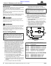
Hydraulic Hook-Up
!
CAUTION!
Do not over speed PTO. The cutter can be damage when
operated above its rated PTO RPM.
1. If the cutter is equipped with a hydraulic cylinder for
height control, locate the hose from the cylinder, and
plug it into one of your tractor’s hydraulic outlets. This
is a one way cylinder, and as such, you only have one
hydraulic hose operation. You will now be able to
operate this cylinder from your tractor’s hydraulic
lever.
2. The offset hydraulic cylinder is a two way cylinder, and
as such, will have two hoses. Plug each hose into a
set of outlets. You now can offset your cutter left or
right by using your tractor’s hydraulic lever.
Un-Hooking from the Tractor
1. Park cutter on a level solid hard surface. Place tractor
gear selector in park and set park brake.
2. Engage parking brake, shut tractor engine off and
remove switch key before dismounting from tractor.
3. Lower deck to level ground or onto blocks supporting
the deck just above ground level.
4. Disconnect hydraulic hose from tractor duplex outlet.
5. Disconnect any safety chains that may be connected
to the tractor. (i.e. driveline safety chain and check
chains)
6. Disconnect driveline from tractor PTO shaft.
7. Unhitch cutter from tractor 3-point arms and center
link if center link is used.
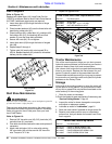
IMPORTANT: A small chain is supplied with the
driveline. This chain must be attached to the inner
driveline shield and to the cutter to restrict shield
rotation.
IMPORTANT: Do not engage tractor PTO until PTO
driveline is fully connected andhydraulic fluid hasbeen
added to the reservoir.
IMPORTANT: Always engage parking brake, shut
tractor engine off and remove switch key before
dismounting from tractor.