


10
Section 1: Assembly and Set-Up
RCS3596, RCSM3596, RCS3510 & RCSM3510 Series Rotary Cutters 312-708M
6/26/06
Land Pride
Table of Contents
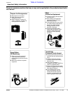
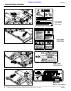
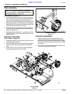
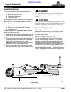
Hitch Assembly
Refer to Refer to Figure 1-1:
1. Install the offset arms (#2) to the cutter making sure
the pinch decals on the arms are to the top and front of
the cutter and assemble the mounting caps (#5).
Secure with bolts (#7) lockwashers (#11) and nuts (#9).
2. Assemble the hitch (#1) to offset arms (#2) inserting
the tubes (#6) in the offset arms and secure with bolts
(#8) lockwashers (#12) and nuts (#10).
3. Assemble rod end of cylinder (#3) to hitch lug with pin
(#13). Cylinder’s hydraulic elbows should be facing
away from offset arms.
4. Assemble the lift cylinder (#3) or ratchet jack (#14) to
lift lug on the deck and the rear axle and secure with
pins as shown.
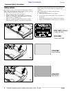
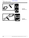
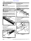
Tailwheel Assembly
Refer to Refer to Figure 1-2:
1. Assemble tailwheel arms (#3) to rear axle with u-bolts
(#7) and flange nuts (#4).
2. Install tailwheel washer (#2) (larger diameter washer)
on the tire yoke (#1) and insert yoke into tailwheel
arms.
3. Place washer (#5) on yoke on top side of tailwheel
arms (#3) and secure with roll pin (#6).
NOTE: Do not tighten hardware until assembly
is complete. Refer to “Torque Values Chart for
Common Bolt Sizes” on page 28.
Tailwheel Assembly
Figure 1-2
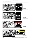
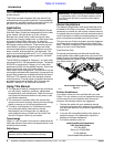
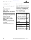
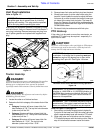
Driveline Installation
1. Attach the slip-clutch end of the driveline to the
gearbox input shaft securely. Make certain that the
slip-clutch is fully onto the input shaft splines. Tighten
the conical dog pin on back side of slip-clutch to 45-50
ft-lb torque.
2. Secure the chain on the driveline to the driveline cone
to restrict outer shield from rotating.
20703
Hitch Assembly
Figure 1-1
20702