


12
Section 1: Assembly and Set-Up
RCS3596, RCSM3596, RCS3510 & RCSM3510 Series Rotary Cutters 312-708M
6/26/06
Land Pride
Table of Contents
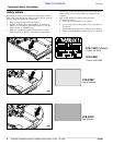
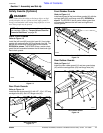
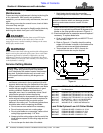
Vent Plug Installation
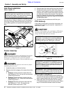
Refer to Figure 1-7:
A vent plug for the splitter gearbox is included in a bag
with the manual. See your nearest Land Pride Dealer if
vent plug is missing. Remove temporary red plug from
top of splitter gearbox and replace with supplied vent
plug.
Vent Plug Location
Figure 1-7
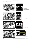
Tractor Hook-Up
!
DANGER!
Crushing Hazard between tractor and implement. Do not allow
anyone to stand between the tractor and implement while
backing-up to an implement. Never operate the hydraulic
3-point lift controls while someone is directly behind the tractor.
!
DANGER!
Engage parking brake, shut off tractor and remove key before
dismounting from the tractor.
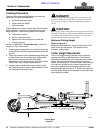
1. Locate the cutter on a flat level surface.
2. Determine the hitch category of the tractor that will be
used:
a. Category I tractors will have a lower hitch link
hole diameter of 7/8”. The top link hole diameter
(cutter end) will be 3/4".
b. Category II tractors will have a lower hitch link
hole diameter of1 1/8”. The top link hole diameter
(cutter end) will be 1".
c. Category III tractors will have a lower hitch link
hole diameter of 1 7/16”. The top link hole
diameter (cutter end) will be 1 5/16".
IMPORTANT: Cutters are shipped with a red plug in
the splitter gear box to prevent loss of oil during
shipping and handling. This plug must be replaced
with a vent plug before operating the cutter.
3. Remove lower linch pins and hitch pins from the deck.
4. Slowly back tractor up to the cutter while using the
tractor’s 3-point hydraulic control to adjust the lower
link arms up or down to match the tractor’s lower arm
pin holes to the cutter hitch pin holes. The lower lift
arms of a Category 2 tractor will be positioned to the
outside of the cutters lower hitch lugs on RCS35596 &
RCSM35596 cutters.
5. Re-insert hitch pins and secure with linch pins.
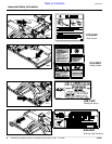
PTO Hook-up
If the cutter is to be used on more than one tractor, an
additional PTO shaft may be required - especially if a
quick hitch is used.
!
CAUTION!
Do not use a PTO adaptor with a quick hitch. A PTO adapter
will increase the strain on the tractor’s PTO shaft and can
damage the PTO shaft and mower driveline.
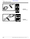
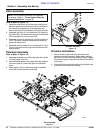
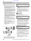
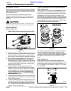
Maximum PTO driveline Movement During Operation
Figure 1-8
Refer to Figure 1-9 on page 13:
1. Start tractor and slowly engage tractor’s hydraulic
3-point to lift the lower arms until the cutter’s driveline
shaft is approximately level with tractor's PTO shaft.
2. Slide outer yoke end of driveline over the tractor's
PTO shaft and secure with the locking collar. Skip to
step 4 if driveline fits between tractor and cutter.
IMPORTANT: Avoid premature driveline
breakdown. A driveline that is operating must not
exceed an angle of 25 degrees up or down while
operating the 3-point lift. See Figure 1-8 below.
13800
IMPORTANT: Do not attempt to operate a 540 RPM
driveline at 1,000 RPM or a 1,000 RPM driveline at
540 RPM. Many tractors provide both 540 and 1,000
RPM PTO speeds. Check your tractor’s manual to
determine its capabilities.
IMPORTANT: The PTO driveline may be too long for
some tractors. If the cutter is used on more than one
tractor, an additional PTO driveline may be required.