25
Section 6: Operating Procedures
4/28/08
RCP2560 & RCPM2560 Series Parallel Arm Rotary Cutter 316-057M
Land Pride
Table of Contents
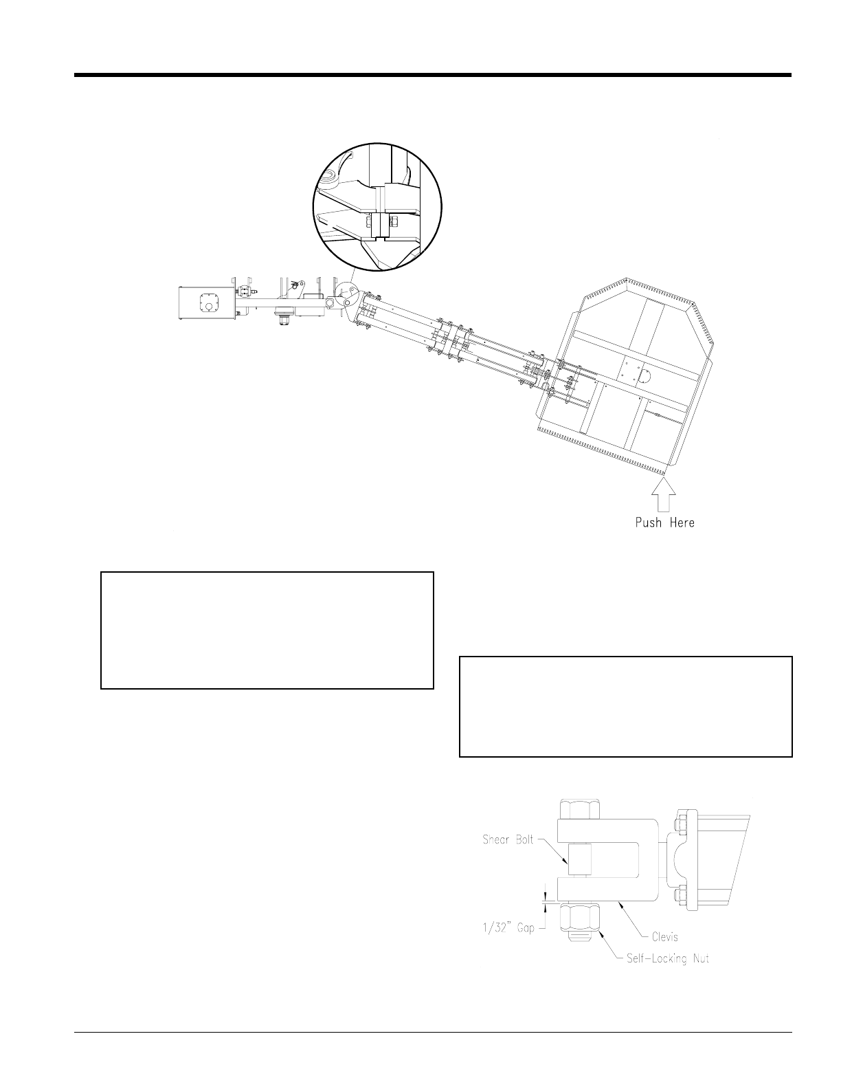
3. Push the deck forward until the breakaway plate
reaches the stop plate. See Figure 6-2. Replace
the tension bolt.
IMPORTANT: Do not back the tractor to reset the deck
to “home” position. Doing so may cause severe
structural damage to the mainframe.
Breakaway Cylinder
1. Raise the arms and deck upward to clear any
obstacles located behind the cutter deck.
2. Slowly back the tractor and cutter away from those
obstacles that would interfere with rotating the
deck and arms to the “home” position.
3. Use the tractor’s remote (cylinder) control to rotate
the deck/arms back to the “home” position.
A shear bolt is located at the rod end of the (optional)
breakaway cylinder. This bolt may shear under the
following conditions:
1. After breakaway, the operator backs the tractor
away from the obstruction, but encounters an
additional obstruction or immovable object while
operating the tractor in reverse. Specifically, the
operator failed to raise the deck high enough to
clear the object before operating the tractor in
reverse.
2. The operator tried to reset the deck/arms by
backing the tractor into an obstruction rather than
using the tractor’s remote cylinder control.
3. The shear bolt has become fatigued after repeated
breakaway cycles and resets.
4. The self-locking nut used to hold the shear bolt in
place has been torqued to the point of contacting
the rod end of the cylinder and, because of
preloading causes the shear bolt to shear with
reduced effort.
IMPORTANT: Do not attempt to operate the
cutter in reverse. The breakaway mechanism will
function ONLY when the tractor is moving in a
forward direction. Cutter operation with the tractor in
reverse gear may cause structural damage to the
parallel arms if the cutter head strikes a solid or
immovable object.
In the event of shear bolt failure, the shear bolt MUST
be replaced with the correct replacement part (316-
118D). The use of a substitute part may result in
damage to the parallel arms or main frame. A single
replacement part is included with each cutter and is
located on a bracket adjacent to the upper 3-point
hitch.
IMPORTANT: Torque the self-locking nut onto the
shear bolt, but do not turn it so far as to make
contact with the clevis of the hydraulic cylinder. In
other words, the nut should be threaded onto the
shear bolt to within approximately 1/32" of contact
with the clevis. See Figure 6-3.
13403
Shear Bolt Space
Figure 6-3
12267
Breakaway Manual Reset
Figure 6-2


