


14
Section 2: Assembly & Set-up
RCP2560 & RCPM2560 Series Parallel Arm Rotary Cutter 316-057M
4/28/08
Land Pride
Table of Contents
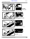
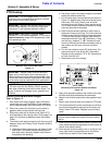
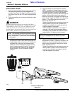
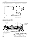
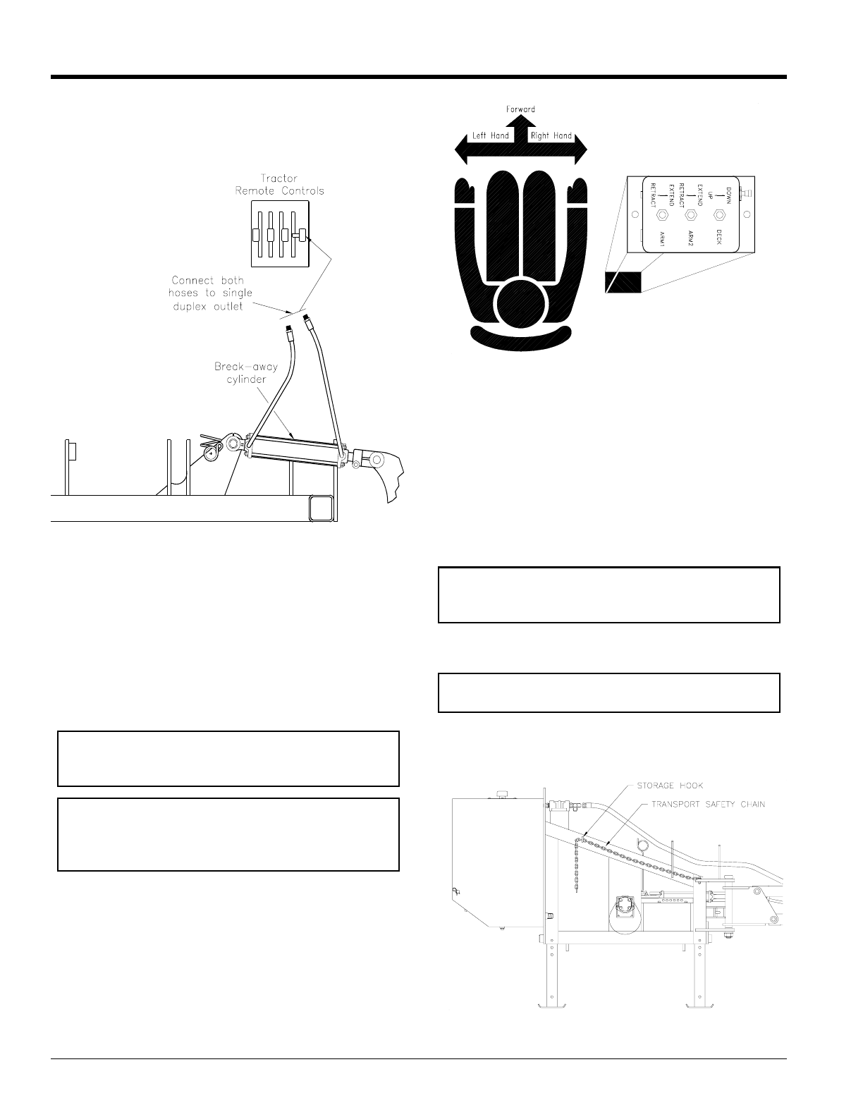
c. See Figure 2-7: If the cutter is equipped with the
optional breakaway cylinder, two additional hoses
will be connected to a single duplex outlet on your
tractor.
2. Add 35 gallons of hydraulic fluid to the hydraulic
reservoir. Use any high quality mineral based
hydraulic fluid such as Mobil fluid 424 with a viscosity
rating of 10W-30. Use care to ensure that dust or
other foreign particles do not contaminate the fluid or
reservoir. Check the fluid level by inserting the
dipstick and cap all the way into the filler tube.
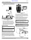
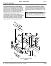
Electrical Hookup
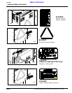
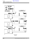
See Figure 2-8: Find a suitable location for the Switch
Control Box. Based on our experience, the location
should be close to the right hand side of the operator -
most generally on the tractor fender or fender console.
Exact location should be convenient to the specific
operator. Orient the Control Box such that the switches
are relative to the movement of the deck and parallel
arms. I.e., when the switch is toggled, the arms or deck
should move in the same relative direction as the handle
of the switch.
Breakaway Cylinder Hose Connections
Figure 2-7
12256
NOTE: If the tractor has dual 6 volt batteries, see
the tractors owners manual for proper 12 volt
hook-up.
IMPORTANT: All dual 6 volt batteries are not
hooked up correctly cylinders may not function
properly due to solenoid valves not being fully
charged. Arm and deck functions will be slow.
Mount the Switch Control Box using either sheet metal
screws (for plastic type consoles) or machine screws,
nuts and washer. Route the control cable to the Solenoid
Control Box and connect the circular plastic connector to
the mating connector on the box.
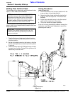
See Figure 2-4 on page 13. Route the power cable to the
tractor battery or circuit breaker panel. A 10 Amp or
larger fuse/circuit breaker source should be used.
Connect the red lead to the positive power source.
Connect the black lead to the negative source.
Ensure that the 10 Amp circuit breaker located on the
switch control box is pushed in prior to functional check.
Determine if tractor is “OPEN” or “CLOSED” Center
Hydraulic System. If unsure consult your tractors owners
manual and/or contact your tractor dealer.
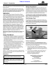
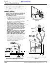
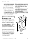
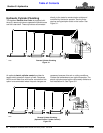
Deck Safety Chain
Figure 2-9
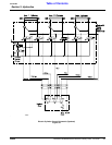
Electric Switch Control Box
Figure 2-8
12257
IMPORTANT: Connect leads to 12VDC power
source only. Connection to 24VDC or larger will
damage electrohydraulic components.
IMPORTANT: This section only applies to Units with
Solenoid Control Valve Option.
12443