


12
Section 2: Assembly & Set-up
RCP2560 & RCPM2560 Series Parallel Arm Rotary Cutter 316-057M
4/28/08
Land Pride
Table of Contents
PTO Hookup
Maximum PTO driveline Movement
Figure 1-4
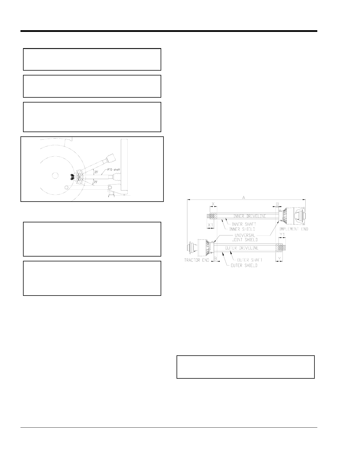
Check Driveline Minimum Length
Refer to Figure 1-5
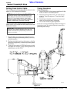
1. Start tractor and slowly engage 3-point controls to
move lower arms until the Rotary Cutter’s gearbox
shaft is approximately level with tractor's PTO shaft.
2. Slide inner yoke of the driveline over the cutter’s
gearbox shaft and secure with locking collar.
3. Slide outer yoke end of driveline over tractor PTO
shaft and secure with locking collar. Skip to step 5 on
page 12 if driveline fits between tractor and Rotary
Cutter.
4. The driveline will require shortening if it is too long tofit
between tractor and Rotary Cutter. Shorten driveline
as follows:
a. Raise/lower 3-point lower arms until Rotary Cutter
and tractor PTO shafts are approximately level
with each other. Securely support cutter frame in
this position with blocking.
IMPORTANT: Do not engage tractor PTO until
driveline is fully connected and hydraulic fluid has
been added to the cutter reservoir.
IMPORTANT: A quick hitch may be used, but is not
recommended because it moves the cutter deck
back about 5" and impedes operator visibility.
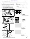
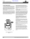
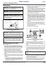
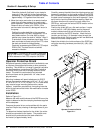
IMPORTANT: See Figure 1-4 below. Avoid
premature PTO driveline breakdown. PTO driveline
must not exceed an angle of 25 degrees up or down
while operating cutter.
13800
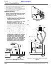
IMPORTANT: Always check driveline minimum
length during initial setup, when connecting to a
different tractor and when alternating between using
a quick hitch and a standard 3-point hitch. More than
one driveline may be required to fit all applications.
IMPORTANT: Itis necessary to aligning the tractor’s
PTO shaft level with the Rotary Cutter’s gearbox
shaft when checking driveline minimum length. Too
long a driveline can damage tractor, gearbox and
driveline.
b. Set tractor in park, shut tractor engine off, set park
brake and remove switch key.
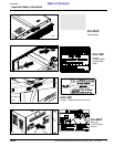
c. Pull driveline apart into two sections as shown in
Figure 1-5. Attach outer driveline universal joint to
the tractor PTO shaft. Attach inner driveline
universal joint to the Rotary Cutter gearbox shaft.
Pull on each driveline section to be sure universal
joints are secured to the shafts.
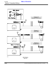
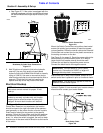
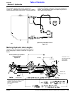
d. Hold driveline sections parallel to each other to
determine if they are too long. The inner and outer
shields on each section should endapproximately
1" short of reaching the universal joint shield on
the adjacent section (see “B” dimension). If they
are too long, measure 1" (“B” dimension) back
from the universal joint shield and make a mark at
this location on the inner and outer driveline
shields.
e. Cut off inner shield at mark (“X” dimension). Cut
same amount off inner shaft (“X1” dimension).
Repeat cut off procedure (“Y”&“Y1” dimensions)
to outer driveline half.
f. Remove all burrs and cuttings.
Shortening PTO Driveline Shields and Shafts
Figure 1-5
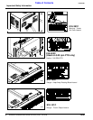
5. Apply multi-purpose grease to the inside of the outer
driveline shaft and reassemble the two shafts.
6. Attach inner driveline yoke to the cutter gearbox input
shaft.
7. Attach outer driveline yoke to the tractor's PTO shaft.
8. The driveline should now be moved back and forth to
insure that both ends are secured to the tractor and
Rotary Cutter PTO shafts. Reattach any end that is
loose.
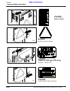
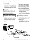
9. Hook one of the driveline safety chains in a holeon the
outer yoke shield and the opposite end tothe tractor to
restrict outer shield rotation.
10. Hook second driveline safety chain in a hole on the
inner yoke shield and opposite end to the Rotary
Cutter frame to restrict inner shield rotation.
IMPORTANT: Two small chains supplied with the
driveline must be attached to restrict driveline shield
rotation.