


16
Section 2: Assembly & Set-up
RCP2560 & RCPM2560 Series Parallel Arm Rotary Cutter 316-057M
4/28/08
Land Pride
Table of Contents
Check the hydraulic fluid level in your tractor's
reservoir. If low, add fluid to the system before
proceeding. The cylinders and hoses will require
approximately 1 3/4 gallons from the tractor.
d. Move the tractor and cutter to a remote location
(away from all other persons) to check pump/
motor operation. Check to be sure the Hydraulic
Reservoir shut-off valve is full OPEN. If this
service valve is turned off, damage will occur to
the pump.
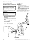
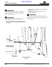
Position the cutter deck flat on the ground or
concrete surface. SLOWLY engage the PTO to
start blade rotation. On initial start-up, blade
position may cause the deck to “vibrate”. After 2-
3 revolutions, these vibrations should stop. If the
deck continues to vibrate, shut off the PTO, raise
the deck and check for locked blades.
Gradually increase engine RPM until PTO output
RPM is 540. The deck should not exhibit
excessive vibration.
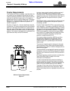
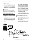
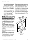
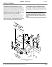
Operator Protective Shield
An optional operator protective shield is available for use
on tractors not equipped with cabs or other protective
shielding. This shield is a "universal" type and is suitable
for attachment to a conventional Roll Over Protective
Structure (ROPS) bar that is already attached to the
tractor. The shield is constructed of an extruded
aluminum frame and is glazed with 1/4" clear, lexan
polycarbonate.
Mounting hardware will permit attachment to ROPS
having cross-section dimensions of 2" x 4", 2" x 5", and
2" x 6" or 2 1/2" x 4", 2 1/2" x 5 and 2 1/2" x 6. Other sizes
may require longer mounting bolts and/or custom
flatbars. Installation requires that 4 mounting holes be
drilled in the frame of the shield. No modification is made
to the ROPS.
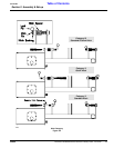
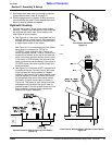
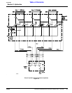
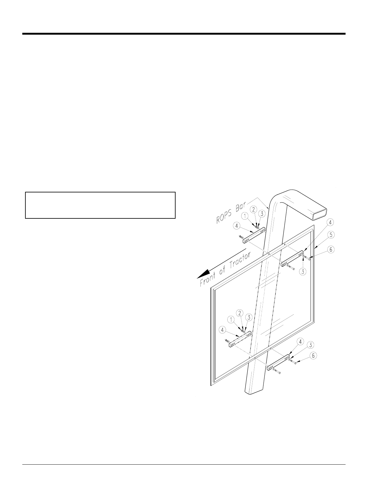
Installation
Refer to Figure 2-11:
Measure the width and thickness of the ROPS bar on the
tractor to determine that the clamping hardware supplied
will be adequate.
Compare the parts list on and quantities with the parts
received. Report any missing or damaged items to your
dealer.
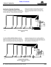
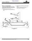
To determine the best location for the shield, the cutter
should be connected to the tractor. The parallel arms
should be fully extended and the deck should be
horizontal (or approximately level).
IMPORTANT: If the tractor being used is equipped
with a 1000 RPM PTO output, be sure that throttle
RPM is reduced to limit PTO output to 540 RPM.
Carefully remove the shield from the shipping carton and
temporarily position it on the inside surface of the ROPS
bar. Locate the shield forward/back, up/down to provide
the best overall coverage for the tractor operator. Use a
spirit level to level the shield before marking. Mark the
top frame location with a pencil on each side of the
ROPS bar, and mark the vertical ROPS location on the
frame of the shield.
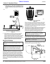
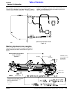
Position the shield (#5) on a flat work surface. Locate
one of the 316-116D (#4) flatbars next to the pencil
marks to determine which set of holes will clear the
vertical marks for the ROPS location. Mark the hole
location and drill two 1/4" diameter holes through the
frame of the shield. Similarly mark and drill two additional
holes for the lower clamp location.
Attach the shield to the inside surface of the ROPS bar
using the mounting hardware provided (#1), (#2), (#3),
and (#6).
Operator Protective Shield
Figure 2-11
13239