


13
Section 2: Assembly & Set-up
4/28/08
RCP2560 & RCPM2560 Series Parallel Arm Rotary Cutter 316-057M
Land Pride
Table of Contents
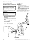
11. Start tractor and raise cutter just enough to remove
support blocks used in step 4a on page 12.
12. Slowly engage tractor’s hydraulic 3-point controls to
raise and lower the cutter. Check drawbar clearance.
Move or remove drawbar as needed.
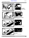
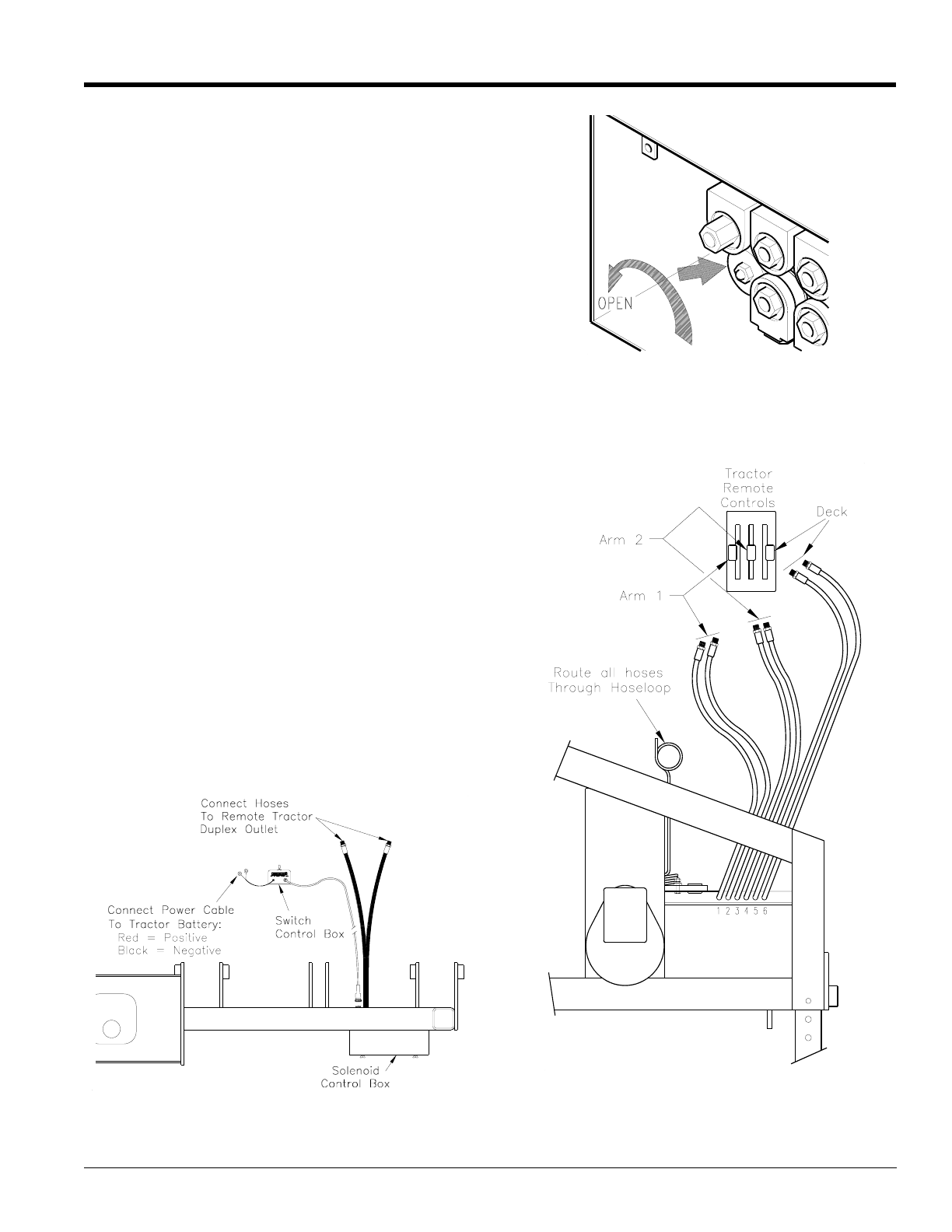
Hydraulic Hookup
1. Connect the hydraulic hoses to the tractor duplex
outlet(s). “Pioneer” quick disconnect hose couplings
are supplied with each hose. Some tractors use
other types of quick couplers.
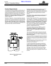
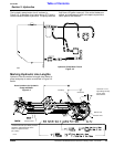
a. See Figure 2-4: If the cutter is equipped with the
optional electric cylinder control, two hoses from
the solenoid valve control box will be attached to
a single duplex outlet on the tractor.
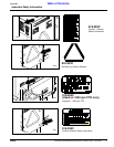
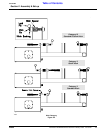
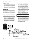
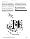
See Figure 2-5: You must determine if the tractor
being used is configured for “OPEN” or
“CLOSED” center hydraulic flow. Consult the
tractor operator's manual if unsure. Remove the
access cover located at the rear of the solenoid
valve control box to adjust the flow control valve.
If the tractor is OPEN center, the valve must be
open (turn knob counterclockwise). Ifthe tractor is
CLOSED center, the valve must be closed (turn
knob clockwise).
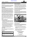
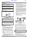
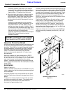
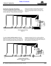
b. See Figure 2-6: If the cutter is NOT equipped with
the optional Electric Cylinder Control, six hoses
(2 per cylinder) will be connected to 3 duplex
outlets on your tractor. Each tractor duplex outlet
must be capable of infinite, variable flow control
by the operator and should have center detent
(off) levers. A typical tractor setup is shown in
Figure 2-6. The hoses on each outlet should be
connected such that when the control lever is
pushed “forward”, the arm (or deck) extends. If the
levers operate in reverse, simply reverse the
hoses at the duplex receptacle.
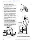
Optional Electrical Control Hook-Up (S/N 163695-)
Figure 2-4
12253
Flow Control Valve Knob
Figure 2-5
12374
Hose Hookup Without Electric Cylinder Control Option
Figure 2-6
12255