19
Section 4 Maintenance and Lubrication
7/18/08
DM35 Series (S/N253045+) Disc Mowers 309-502M
Land Pride
Table of Contents
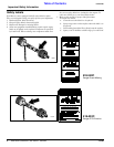
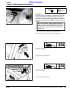
3. Apply sealant to the shaft assembly housing. Attach
the shaft assembly housing to the cutter bar
maintaining parallel alignment of the reference mark
and cutter bar.
4. Install the disc on the shaft perpendicular to the
adjacent discs.
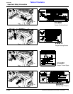
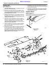
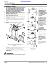
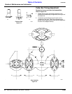
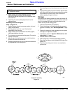
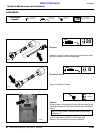
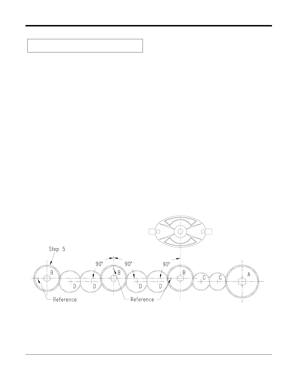
Assembly of entire cutting bar.
Refer to Figure 5-4:
1. Carefully clean all parts to remove sealant, dirt, and
metal contamination.
2. Set the gearbox onto the cover. Set the shaft
assemblies onto the cover.
3. Apply sealant to the underside of the shaft support
housing and tighten the nuts.
4. Turn the cover over and set the idler gears (C) onto the
inserts in the cover.
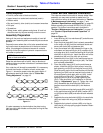
5. Align the punched reference mark on the first pinion
(B) with the center line of the bar.
6. Rotate the second pinion until the punched reference
is perpendicular to the first pinion.
NOTE: The reference punch mark is round. Ignore
any rectangular marks.
7. Alternate alignment of the reference marks down the
bar.
8. Place the idler gears (D) into the inserts. Set the lower
half of the cutter bar on the cover and seal the contact
areas between the two halves. Wait a few hours
before applying the gear lubricant.
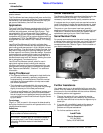
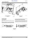
Storage
At the end of the working season or when the mower will
not be used for a long period, it is good practice to clean off
any dirt or grease that may have accumulated on the
mower and any of the moving parts.
1. Clean the Disc Mower as necessary.
2. Check the blades and blade fasteners for wear and
replace if necessary, see “Servicing Blades”, Page
17.
3. Inspect the mower for loose, damaged or worn parts
and adjust or replace as needed.
4. Lubricate as noted in “Section 4 Maintenance and
Lubrication” on page 17.
5. Release tension on drive belts.
6. Store cutter bar in horizontal (operating) position.
7. Store the Disc Mower inside if possible for longer Disc
Mower life.
8. Repaint parts where paint is worn or scratched to
prevent rust.
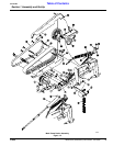
Cutter Bar Assembly
Figure 5-4
10441