


10
Section 1 Assembly and Set-Up
DM35 Series (S/N253045+) Disc Mowers 309-502M
7/18/08
Land Pride
Table of Contents
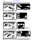
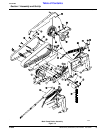
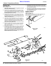
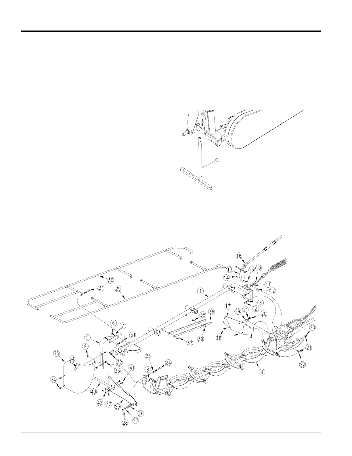
7. Assemble the front tarp frame (#29) and rear tarp
frame (#30) to the support frame (#1) using bolts (#31)
and nuts (#32) to secure.
8. Assemble the shield (#33) to the support frame (#1)
and support leg (#5) using the carriage bolts (#34)
and nuts (#35) to secure.
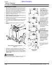
Support Stand
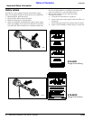
Refer to Figure 1-4:
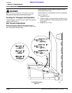
Insert stand (#1) into tube on the hitch as shown and
secure with pin (#2) and hair pin cotter (#3).
Support Stand
Figure 1-4
17895
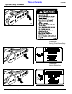
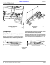
Cutting Unit
Refer to Figure 1-3:
1. Install the support frame (#1) to the gearbox using the
bolts (#2) and washers (#3).
2. Assemble the support leg (#5) to the support frame
(#1) using the bolts (#6) and washers (#7). Assemble
the support leg (#5) to the cutting unit (#4) and secure
with bolt (#8) and lock nut (#9).
3. Assemble the clevis (#11) on the support frame lug
and retain with pin (#12) as shown.Loosen nut on D-
ring (#10) that is at the end of the spring stretcher and
install on the clevis (#11).
4. Install the cylinder bracket (#13) on to the support
frame (#1) using the pin (#14) and hair pin cotter (#15)
to secure. Assemble the other end of the cylinder
(#16) to the cylinder bracket (#13) and secure with pin
(#14) and hair pin cotter (#15).
5. Attach the shield (#17) as shown using the brackets
(#19) and (#22). Secure with bolts (#18), washers
(#21) and nuts (#20).
6. Assemble the guide (#23) to the cutting unit (#4) with
the bolt (#24), washer (#25), flat washer (#27) and
lock nut (#28). Place the spring (#26) between the
guide (#23) and flat washer (#27).Attach the guide rod
(#40) to the guide (#23) with the carriage bolts (#41),
washers (#43) and lock nuts (#42).
17878
Cutting Unit
Figure 1-3