


8
Section 1 Assembly and Set-Up
DM35 Series (S/N253045+) Disc Mowers 309-502M
7/18/08
Land Pride
Table of Contents
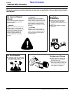
Tools Required
•
Fork lift, crane hoist or block-and-tackle
• Impact wrench or socket and ratchet set (metric)
• Rubber mallet
• Box-end (metric), allen (metric) and crescent wrenches
• Drift pins
• Screwdriver
• Safety shoes, safety glasses and gloves. A hard hat
should be worn by anyone working under the crane.
Assembly Preparation
Having all the parts and equipment readily at hand will
speed up your assembly task and make the job as safe as
possible.
Prepare the area where the unit is to be assembled mak-
ing sure the area is swept clean of all dust and contami-
nants. Un-package the crate and remove all contents
carefully so that the seals on hydraulic components are
not broken or pulled off.
Raise the mainframe with a forklift, hoist or block-and-
tackle and place on pallets or blocks so it is elevated about
10” off the floor.
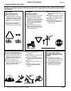
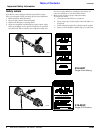
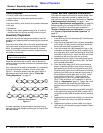
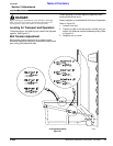
Your cutter bar will already be assembled. It is necessary
to check the direction of rotation of each cutter plate.
Figure 1-1 shows the proper cutter bar plate rotation. If
adjustments need to be made, refer to “Cutter Bar
Timing Adjustment” on page 18.
It is also necessary to check whether the plate turning
right has right cutter blades and the plate turning left has
left cutter blades.
NOTE: Remove heavy components from crate with a
hoist or block-and-tackle.
Cutter Bar Plate Rotation
Figure 1-1
15144
Cutter Bar and Gearbox Lubrication
The cutter bar should arrive with oil already added. After
assembly you may want to check to make sure. For
instructions on how to do this see Lubrication in “Section
4 Maintenance and Lubrication” on page 17 and
“Section 5 Specifications and Capacities” on page 22.
Before operating this unit add SAE 80 GL4 (EP) oil to
gearbox. For further instructions see Lubrication in
“Section 4 Maintenance and Lubrication” on page 17
and “Section 5 Specifications and Capacities” on
page 22.
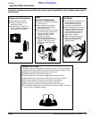
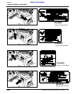
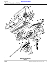
Refer to Figure 1-2:
1. Insert bushing (#1) into mainframe (#7) and slide over
gearbox as shown.
2. Insert the pivot plate (#43) that is already assembled
to the cutter unit (#2) onto the mainframe studs and
secure with bolts (#3) and washers (#4).
3. Insert the release arm (#8) between the lugs on the
mainframe and secure with pin (#12), washers (#13)
and cotter pins (#14). Install the bushing (#10) and the
chain(#9) on the hitch pin. Insert the other end of the
release arm (#8) on to the hitch pin as shown.
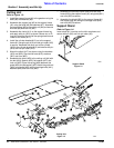
4. Assemble the tie rod (#41) to the mainframe lugs as
shown using the pin (#5) and roll pin (#6). The other
end is already assembled.
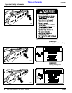
5. Place the pulley mount (#15) on the mainframe as
shown. Install belt (#23) on both pulleys. Insert the
belt tightening rod (#18) into the pulley mount (#15).
Slide the pulley mount on the mainframe until the belt
tightening rod (#18) can be inserted into the hole of
the mainframe lug and retain with nut (#19). Install
u-bolt (#16) and nuts (#17). Tighten the belt by
tightening the nut (#19) on the belt tightening rod
(#18). There should be a 3/4” deflection in the belt.
Refer to “Adjustments” page 15. Tighten the u-bolt
(#16). Assemble the driveline shield (#20) to the
gearbox mount with the bolts (#21) and washers
(#22).
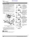
6. Install the bottom and top belt guards (#24) and (#25)
to the mainframe using the bolt (#26), washer (#27),
nut (#33) stud bolts (#28) and external tooth washers
(#29).
7. Assemble the outer belt shield (#32) to the stud bolts
(#28) and retain with wing nuts (#30) and washers
(#31).
8. Assemble the hydraulic cylinder (#39) on to the pin
(#42) that is in the top spring support bracket. Retain
with pin (#40).
Section 1 Assembly and Set-Up