


TP-6069 6/0372 Section 8 Reconnection/Adjustments
7685
11 10 12 9
15 14 16 13
L2
L3
To Generator
Set
To Shore
Power
To Load
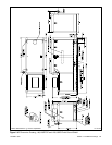
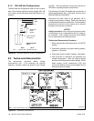
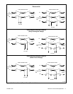
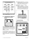
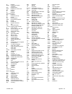
4-Wire, 3-Phase Generator Sets
L0
3241
L1
L2
L3
L0
L1
L2 L3 L0L1
Kraus Naimler/American Solenoid
I-940
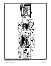
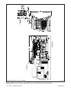
Figure 8-10 Marine Manual (Ship-to-Shore) Transfer
Switch, continued
8.4 Voltage Regulator Adjustment
(4--27EFOZ and 5--32EOZ
Models)
Hazardous voltage.
Can cause severe injury or death.
Operate the generator set only when
all guards and electrical enclosures
areinplace.
Movingrotor.
WARNING
Testing the voltage regulator. Hazardous voltage can
cause severe injuryor death. High voltage ispresent atthe
voltageregulator heat sink. Topreventelectrical shock donot
touch the voltage regulatorheat sink whentesting the voltage
regulator.
(PowerBoostt, PowerBoostt III, and PowerBoostt V
voltage regulator models only)
The voltage regulator is typically located in the
controller. Adjustments are possible without removing
the voltage regulator. The voltage regulator adjustment
procedure applies to both the PowerBoost IIIE
(Figure 8-11) and PowerBoostV (Figure 8-12) voltage
regulators.
Note: Broadrange generator sets. The following
adjustment procedure is for readjustment of the
voltage regulator and governor for broadrange
generator sets with mechanical governors.
Note: Special tool. Frequency meter 50/60 Hz.
Note: Rheostat connection. Connect a
customer-provided rheostat across regulator
leads/terminals 33 and 66 to adjust the generator
output voltage from a location remote from the
generator set. The rheostat (10 kOhms, 1/2 watt
minimum) provides a 5-volt adjustment range.
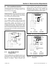
TT-875-11
1
2
3
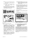
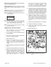
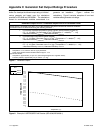
1. Voltage adjustment potentiometer
2. Stability adjustment potentiometer
3. Volts/Hz adjustment potentiometer
Figure 8-11 PowerBoost IIIE Voltage Regulator
8
7
6
5
4
3
2
1
VOLTSV/HZ
STAB
TT-875-11
2
3
1
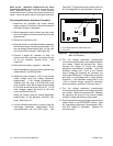
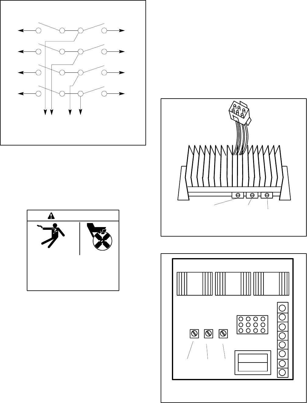
1. Voltage adjustment potentiometer
2. Stability adjustment potentiometer
3. Volts/Hz adjustment potentiometer
Figure 8-12 PowerBoost V Voltage Regulator