


TP-6069 6/036 Section 3 Cooling System
Do not use a speed scoop or cup design intake
through-hull strainer because it can cause a ramming
effect and force water upward, past the seawater pump,
and into the engine cylinders when the vessel is moving
and the generator set is shut down.
Do not use hulls incorporating sea chests or other
designs that provide apositive pressure to the raw water
pump for the intake through-hull strainers. Positive
pressure forces water past the raw water pump and into
the engine. A sea chest is a concave molded-in-the-hull
chamber that aligns to the vessel’s direction of travel. A
sea chest configuration applies positive pressure similar
to a scoop-type through-hull strainer.
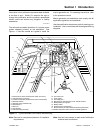
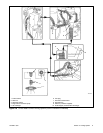
3.2.2 Seacock
Mount the seacock to the hull, assemble it to the intake,
and ensure that itis accessiblefor operation. Figure 3-2
shows a typical installation.
Avoid overcaulking the seacock. Excess caulk reduces
water flow and, in some cases, develops a barrier that
can force water upward, past the seawater pump, and
into the engine cylinders when the vessel is moving and
the generator set is shut down.
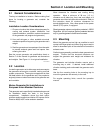
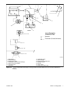
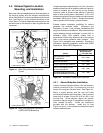
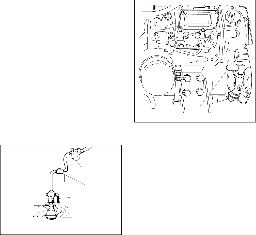
3.2.3 Seawater Strainer
Mount the seawater strainer to the seacock or
permanent structure at a point not higher than the
seawater pump. Ensure that the strainer is accessible
for service. See Figure 3-4 for a typical installation.
Some seawater strainers include a seacock and an
intake through-hull strainer.
Maximumseawater inletpressure at the seawater pump
is 34.5 kPa (5 psi). Excessive pressure will cause water
ingestion.
1
2
3
1-789
1. Seawater pump
2. Seawater strainer
3. Seacock
Figure 3-4 Seawater Strainer
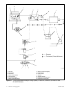
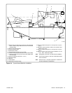
3.2.4 Water Lines
Water lines from the seacock to the engine-driven
seawater pump are usually constructed of flexible hose.
Connect a flexible section of hose to the seawater pump
to allow the generator set to vibrate during operation.
Support a nonflexible water line within 102 mm (4 in.) of
its connection to the flexible section.
Keep the seawater hose as straight and short as
possible. If the hose is too long, usually over 4.6 m
(15 ft.), water draw problems may occur. See Section 7
for the inlet water line hose size and the seawater
connection to the seawater pump inlet. Avoid running
the inlet pipe above the generator. See Figure 3-5 for
the seawater hose connection to the seawater pump
inlet.
1
TP-5586-6
1. Seawater pump inlet
Figure 3-5 Seawater Inlet Connection, Typical
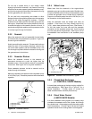
3.2.5 Closed Heat Exchanger
(4--125EFOZ/5--150EOZ Models)
A closed heat exchanger is the best cooling method for
most applications. See Figure 3-6 or Figure 3-7 for a
typical installation. Provide space to access the
water-cooled exhaust manifold pressure cap.
3.2.6 Direct Water Cooled
(3.5EFOZ/4EOZ Models)
In a d irect seawater cooling system, the impeller pump
circulates the seawater around the cylinder and through
the cylinder head. A thermostat controls the cooling water
circuit temperature. Consult F igure 3-8 and the engine
operation manual for the cooling water circuit diagrams.