


TP-6069 6/03 5Section 3 Cooling System
Section 3 Cooling System
3.1 Ventilation
Engine combustion,generator cooling, and expulsion of
flammable and lethal fumes require ventilation. Provide
ventilation compliant with USCG Regulations governing
sizing of vents and other considerations.
As a rule, size each inlet- and outlet-vent area to a
minimum of 13 sq. cm/30.5 cm (2 sq. in. per ft.) of the
craft’s beam. Should this rule conflict with USCG
Regulations, follow USCG Regulations. For applications
with screened inlets, double the size (4 sq. in. per ft.) of
the hull/deckopenings. Extend the vent ducts to bilges to
expel heavier-than-air fumes.
For generator sets mounted inthe enginecompartment,
increase the air flow to allow for the generator set’s
requirements. Install optional detection devices to
cause alarm, warning, or engine shutdown should
dangerous fumes accumulate in the compartment.
See the generator set specification sheet that shipped
with the generator set for air requirements. The air intake
silencer/cleaner provides combustion air to the engine.
Do not compromise the recommended minimum
clearance of 38 mm (1.5 in.) between a duct opening and
enclosure wall. The engine/generator performance will
decline if you compromise these guidelines. See
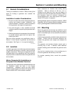
Figure 3-1 for allowable intake restriction.
Note: ISO 3046 derates apply. See Appendix C.
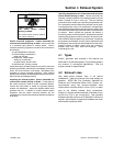
Model Allowable Intake Restriction
3.5EFOZ/4EOZ 200 mm H
2
O (1.96 kPa or less)
4--125EFOZ/5--150EOZ 635 mm H
2
O (6.23 kPa or less)
Figure 3-1 Combustion Air Intake Restriction
3.2 Cooling System Components
The marine generator set’s cooling system requires the
following components.
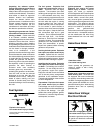
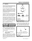
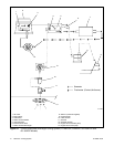
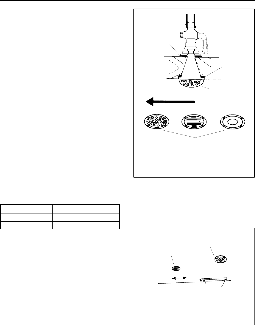
3.2.1 Intake Through-Hull Strainer
(Seacock Cover)
Install a screened-intake, through-hull strainer to
prevent entry of foreign objects. Use perforated,
slotted-hole, or unrestricted-hole design strainers. See
Figure 3-2 for examples of typical strainers. The inner
diameter of the strainer opening must be equal to or
greater than the inner diameter of the water-line hose to
the seawater pump.
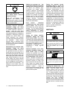
1
2
3
4
5
1-789
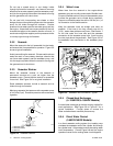
1. Inside packing
2. Outside packing
3. Seacock cover
4. Direction of vessel movement
5. Typical intake through-hull strainers
Figure 3-2 Seacock Installation
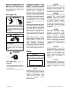
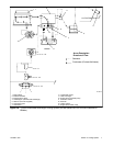
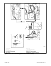
Do not align the strainer (in relation to the craft’s direction
of travel) with any other through-hull intakes. See
Figure 3-3. Flush mount the recommended through-hull
strainer. Install slotted-hole-design strainers with the
slots parallel to the direction of the vessel’s movement.
Note: Position the intakes in relation to the vessel’s
travel so neither is in the wake of the other.
1
2
4 3
1-789
1. Generator set intake
2. Main engine intake
3. Aft (rearward)
4. Fore (forward)
Figure 3-3 Intake Strainer