


TP-6069 6/03 1Section 1 Introduction
Section 1 Introduction
Information in this publication represents data available
at the time of print. Kohler Co. reserves the right to
change this publication and the products represented
without notice and without any obligation or liability
whatsoever.
x:in:001:002:a
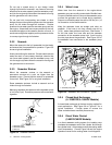
The safe and successful operation of a marine power
system depends primarily on the installation. See
Figure 1-1. Use this manual as a guide to install the
marine generator set. For operating instructions, refer
to the operation manual.
Marine generator set installations must comply with all
applicable regulations and standards.
Use the specification sheets as a guide in planning your
installation. Use current dimension drawings and wiring
diagrams.
KOHLER
1
2
3
4
5
6
7
8
9
10
11
12
13
14
15
16
17
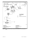
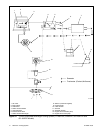
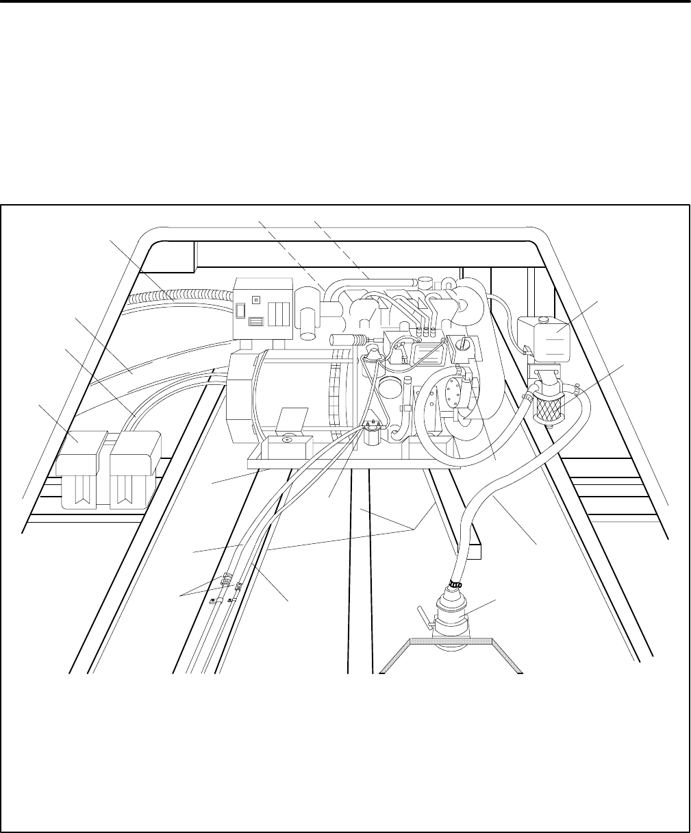
585711
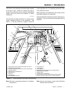
1. Exhaust mixer elbow (exhaust/water outlet) (not shown)
2. Heat exchanger (not shown)
3. Coolantrecoverytank(locatedontheunitonsomemodels)
4. Seawater strainer *
5. Seawater pump (seawater inlet)
6. Seawater line *
7. Seacock *
8. Craft stringers
9. Fuel feed pump (fuel inlet) *
10. Fuel return line *
11. Hose clamps
12. Fuel supply line *
13. Mounting tray (mounting skid on 33--150 kW models)
14. Battery/battery storage box
15. Battery cables
16. Exhaust hose or exhaust line *
17. Electrical leads (AC output leads/remotestart panel leads)
* Indicated components must conform to USCG regulations.
Figure 1-1 Typical Generator Set Location and Mounting
Note: See text for complete explanation of installation
requirements.
Note: Use two hose clamps on each end of all flexible
exhaust hose connections.