


TP-6069 6/03 67Section 8 Reconnection/Adjustments
Section 8 Reconnection/Adjustments
8.1 Four-Lead Reconnection
The following information illustrates the reconnection of
four-lead generator sets. In all cases, conform to the
National Electrical Code (NEC).
NOTICE
Voltagereconnection. Affixanoticetothegeneratorsetafter
reconnecting the set to avoltage different fromthe voltage on
the nameplate. Order voltage reconnection decal 246242
from an authorized service distributor/dealer.
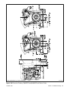
8.1.1 100--120-Volt Configurations
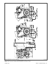
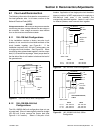
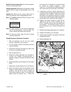
If the installation requires a factory two-pole circuit
breaker, do not connect the load-side terminals of the
circuit breaker together; see Figure 8-1. If the
installation requires a 100--120-volt, 2-wire system, use
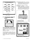
a single-pole circuit breaker. See Figure 8-2. When
connecting stator phase leads together, size the output
lead (L1) to handle the amperage. Use a jumperlead on
the line side of the circuit breaker to balance the load of
the generator set.
GRD.
L1
L2
4321
L0 (Neutral)
L0
Ground
Load
Side
Line
Side
Two-Pole
Circuit
Breaker
Jumper
lead
Figure 8-1 100--120-Volt, 3-Wire Configuration
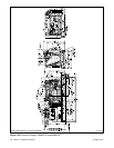
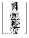
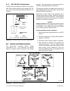
8.1.2 100--120/200--240-Volt
Configurations
The 100--120/200--240-volt configuration does not use
a jumper lead. If the unit was originally wired for straight
100--120 volt, 3-wire, remove the jumper lead (see
Figure 8-1 for location). Select a two-pole circuit
breaker. Application of two single-pole circuit breakers
does not conform to NEC requirements for supplying a
200--240-volt load, even if the breakers are
mechanically attached together. Leads L1 and L2 are
for different phases; never connect them together.
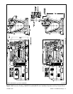
4321
Stator Leads
L0
GRD.
L1
L0 (Neutral)
Line
Side
Single-Pole
Circuit
Breaker
Ground
Load
Side
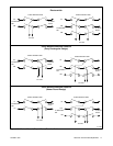
60 Hz 50 Hz
L0--L1 100--120 Volt 100--120 Volt
L0--L2 100--120 Volt 100--120 Volt
Figure 8-2 100--120-Volt, 2-Wire Configuration
4321
Stator Leads
L0
GRD.
L2
L1
L0 (Neutral)
Line
Side
Factory
Two-Pole
Circuit
Breaker
Ground
Load
Side
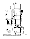
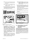
100--120/200--240-Volt,
3-Wire
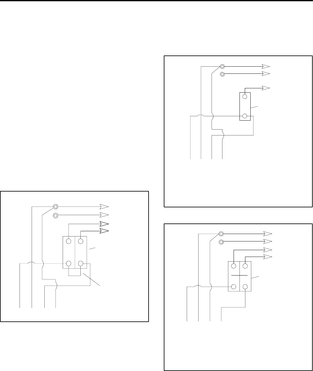
60 Hz 50 Hz
L0--L1 100--120 Volt 100--120 Volt
L0--L2 100--120 Volt 100--120 Volt
L1--L2 200--240 Volt 200--240 Volt
Figure 8-3 100--120/200--240-Volt, 3-Wire
Configuration