


TP-6069 6/0370 Section 8 Reconnection/Adjustments
Short circuits. Hazardous voltage/current can cause
severeinjury or death. Shortcircuits can cause bodily injury
and/or equipment damage. Do not contact electrical
connectionswith tools or jewelry while making adjustments or
repairs. Remove all jewelry before servicing the equipment.
Overvoltage Shutdown Adjustment Procedure
1. Disconnect the generator set engine starting
battery, negative (--) lead first. Disconnect power to
the battery charger (if equipped).
2. With the generator set shut down, open the output
line circuit breaker to disconnect the load from the
generator set.
3. Remove the controller cover.
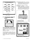
4. Wrap the shaft of an insulated-handle screwdriver
with electrical tape to insulatethe metal shaft. Turn
the overvoltage potentiometer (R41) on the main
circuit board fully clockwise. See Figure 8-8.
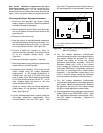
5. Connect a digital AC voltmeter (or other 1%
minimum accuracy voltmeter) to terminals V0 and
V7 on the controller terminal block. See
Figure 8-6.
6. Reconnect the battery, negative (--) lead last.
7. Start the generator setby placing the generator set
master switch in the RUN position.
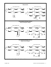
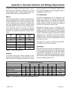
8. Adjust the output voltage to 115% of the nominal
output voltage using the voltage adjustment
potentiometer. If the voltage configuration is
139/240 volts (low wye) or 277/480 volts (high
wye), 3-phase, 4-wire, 60 Hz, adjust output voltage
to 160 volts across terminals V0 and V7. For all
other voltages, adjust the output to 140 volts
across terminals V0 and V7.
Adjust the voltage using the voltage adjustment
potentiometer on the generator controller front
panel. See Figure 8-7.
9. Use the insulated screwdriver to slowly rotate the
overvoltage adjustment potentiometer (R41)
counterclockwise until red LED4 lights. See
Figure 8-8. The generator set should shut downon
an overvoltage fault in approximately 2 seconds.
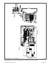
P1
P2
A-336415-A
2
R41
LED4
1. Overvoltage adjustment potentiometer (R41)
2. LED4 (red)
1
Figure 8-8 Overvoltage Shutdown Adjustment on
Main Circuit Board
10. Turn the voltage adjustment potentiometer
counterclockwiseto prevent overvoltageshutdown
upon restart. Restart the generator set. Slowly
increase the voltage by turning the voltage
adjustment potentiometer clockwise. Verify the
shutdown voltage point (115% of the nominal
output voltage) by observing the voltmeter and
noting when LED4 lights. The generator setshould
shut down on overvoltage fault in approximately
2 seconds. If the shutdown voltage point is not
115% of nominal voltage, repeat the calibration
output procedure; otherwise, continue to step 11.
11. Turn the voltage adjustment potentiometer
counterclockwiseto prevent overvoltageshutdown
upon restart. Restart the generator set. Readjust
the generator set output to the nominal voltage
using the voltage adjustment potentiometer.
12. Stop the generator set by placing the generator set
master switch in the OFF/RESET position. Seal
the overvoltage adjustment potentiometer (R41)
with RTV sealant or equivalent. Replace the
controller cover.