


TP-6069 6/0322 Section 6 Electrical System
10. Connect the side of the circuit breaker marked
LOAD to the ship-to-shore switch or craft wiring.
Attach insulation boots to the black leads if the kit
includes insulation boots. With a single-pole circuit
breaker use one black lead (L1). With a two-pole
circuit breaker use two black leads, L1 and L2.
Connect the neutral (white) lead to the L0 stud.
Connect the equipment ground (green) lead to
GRD stud.
Note: Wire material. Use stranded copper for all
wiring. Use wire gauges and insulation,
conductor temperature ratings, sheath
stripping, conductor support and protection,
conductor terminals and splices, and
overcurrent protection (circuit breakers,
fuses) that conform to standards and codes.
Note: Follow USCG Regulations CFR33, Part 183
(Pleasurecraft) and CFR46 (Commercial
Craft) for marine applications.
Note: Wire protection. Use rubber grommets
and cable ties as necessary to protect and
secure wiring from sharp objects, the
exhaust system, and any moving parts.
11. Replace the controller cover or circuit breaker box
access panel.
12. Reconnect the generator set engine starting
battery, negative (--) lead last.
13. Make voltage or frequency adjustments according
to Section 8.
Note: Voltage/frequency adjustable. Some
four-lead generator sets are not
voltage/frequency adjustable. To determine
adjustment possibilities, check the model’s
specification sheet orservice manual. If you
are reconnecting the generator set from a
single-voltage to a dual-voltage
configuration (example: from 120-volt to
120/240-volt) or a dual voltage to a single
voltage (example: from 120/240-volt to
120-volt) with the same primary voltage, do
not adjust the voltage/frequency
adjustment. Adjust the voltage/frequency
for frequency changes or setting changes of
the primary voltage (example: from 120-volt
to 100-volt). Refer to the model’s
specification sheet for reconnection
capability.
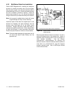
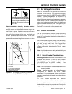
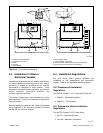
6.2.3 Circuit Breaker Installation
(33--125EFOZ and 40--150EOZ
Models)
1. Place the generator set master switch in the OFF
position.
2. Disconnect the generator set engine starting
battery, negative (--) lead first.
3. Remove the six screws from the right side junction
box panel and remove the panel.
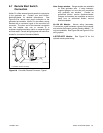
4. Install the circuit breaker on the new panel with the
screws and washers. Position the ON side of the
circuit breaker toward the rear of the junction box.
See Figure 6-4.
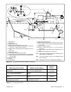
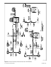
5. Attach stator leads L1, L2, and L3 to the extension
leads (if supplied) or to the line side of the circuit
breaker. See Figure 8-5.
Note: Insulate leads with electrical tape after
connecting extension leads to stator leads.
6. Connect the neutral connection stator leads to the
L0 stud.
Note: Verify that terminal positions and previously
made line lead connections allow room for
load connections to load studs.
7. Connect the load side of the circuit breaker to
customer-supplied craft wiring. Connect the
neutral lead to the L0 stud. See Figure 8-5.
8. Attach the new panel to the junction box using the
original six screws. See Figure 6-4.
9. Check that thegenerator setmaster switchis inthe
OFF position. Reconnect the generator set engine
starting battery, negative (--) lead last.